Maintenance Reference(CP45FV) Eng.pdf - 第126页
Samsung Component Placer CP45FV Series Maintenance Guide T able 7-6. T a king Measur es in case of operational malfunction No Malfunction Checking points Check motor power lines Phase sequence of motor power lines is not…
Inspection of the Controller
Corrective measures
Cause
Corrective measures
1 Faulty amplifier internal circuit Replace servo amplifier.
2 Malfunction due to noise
Check that amplifier earth cable
should be correctly grounded.
Add ferrite core as a countermeasure
against noise.
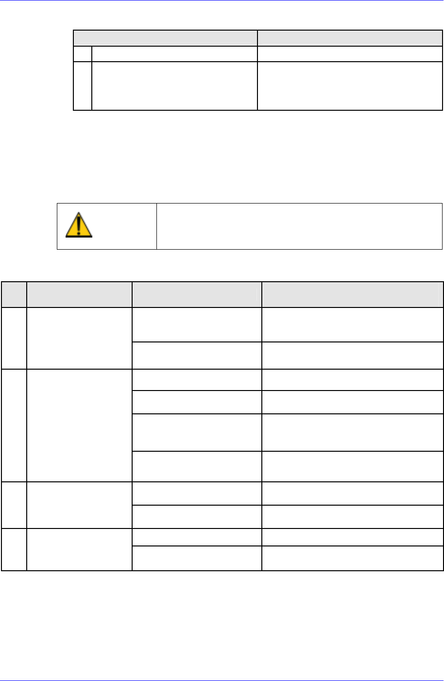
7.9.2. Taking Measures in case of Operational Malfunction
On the occasion of operational malfunction without an alarm, the following explains
checking points, inferable causes, and countermeasures. Consult your Sanyo Denki dealer
should the malfunctions persist even after performing these troubleshooting measures.
Caution
Take note that it is dangerous to perform some of these
procedures without first switching off the main power
supply
Table 7-5. Taking Measures in case of operational malfunction
No
Inferable Causes and
countermeasures
Check voltage of control
power input terminals
1
7-segment LED does
not display “≡“ after
main power supply is
switched on
Check if red “CHARGE”
LED is on
Faulty power supply circuit → Replace
servo amplifier
Check if position command
ii ttd
Input position command.
Check if servo lock is on
Check tightening of screw as motor
power line is not connected
Check if current limit is
inputted
Motor does not rotate, since current
limiter is on and motor cannot generate
torque against the load torque.
2 7 segment LED is
displaying a flashing
“8” (servo ON status),
but motor is not
rotating
Check if deviation clear
remains on
Chancel the deviation clear input (CN1-
34 pin)
Check if proportional
control is on
Stop proportional control input
3
Unstable servomotor
rotation. Lower
rotation than
command.
Check if current limiter is
on.
Stop current limiter input.
Check motor power lines One of the power lines is disconnected.
4
Servomotor rotates
momentarily before
stopping.
Check encoder resolution
setting.
Correct the setting and turn on the
power.
Malfunction Checking points
Check power supply if voltage is low
Check wiring and tightening of
screws if there is no voltage
7-55

Samsung Component Placer CP45FV Series Maintenance Guide
Table 7-6. Taking Measures in case of operational malfunction
No Malfunction Checking points
Check motor power lines
Phase sequence of motor power lines
is not correct
5
Servomotor
accelerates
continuously
Check encoder cable
A and B phases of the encoder are
incorrect.
6
Motor vibrates
at frequencies
over 200Hz.
-
7
Excessive
overshoot/unde
rshoot during
start/stop.
Check for mechanical faults.
8
Abnormal
acoustic noise
Operate at low speed and check
the noise period, random or
frequent.
Inferable Causes and
countermeasures
Reduce velocity loop gain
Set torque command low pass filter
and notch filter.
-
Servo tuning with setting “High”
Lower velocity loop gain ・ Increase
integral time constant ・ Loosen
acceleration / deceleration
command pattern
Use position command low pass
filter
Operate servomotor with no load
Check centering and unbalance on
coupling
Check if encoder signal line is pair-
twisted and shielded.
Check if encoder and power lines
are put together in the same duct.
Check if power supply voltage
drops.
7-56
Inspection of the Controller
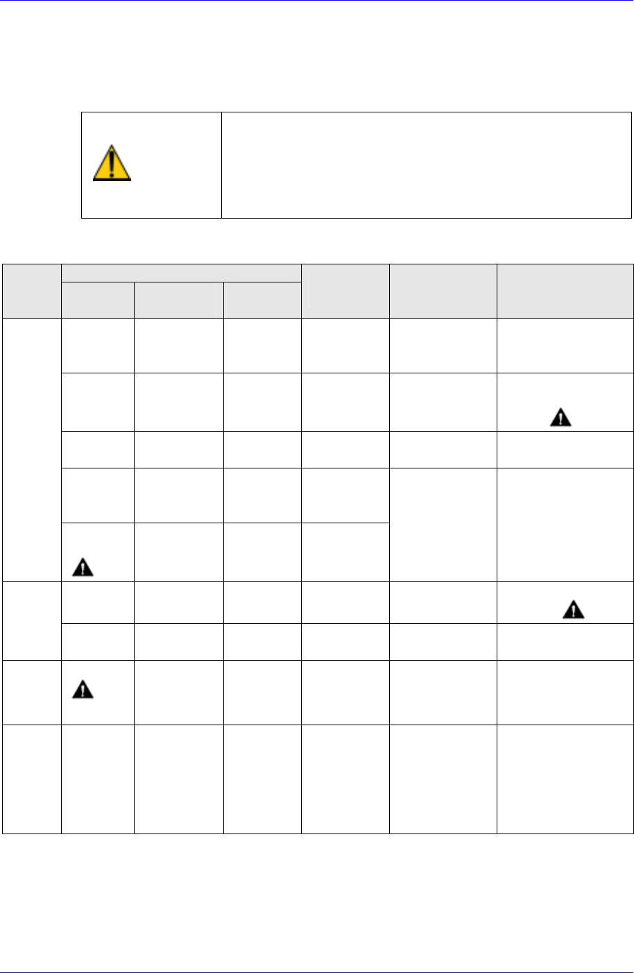
7.9.3. Maintenance
As the Servomotor and amplifier have no wearing parts, the user has only to check
routinely. The check item, timing, and procedure are indicated as follows.
1. Performing of megger test of the Servo Amplifier
may damage the amplifier, we recommend that
you conduct a continuity check using the tester.
Caution
2. Do not remove the cover from the detector of the
Servomotor.
Table 7-7. Inspection Procedure
Check conditions
Check
point
Timing
During
Operation
During
Stopping
Check
item
Check
method
Countermeasures
Routine
○
Vibration
Check if vibration
is larger than
usual
Contact us
Routine
○
Acoustic
noise
Check if abnormal
noise sounds than
usual.
Clean the Servomotor
using a cloth or air
blow. 1
As needed
○
Cleaning
Check for dirt or
dust
Yearly
○
Insulation
resistance
measurement
Servo
motor
Every 5000
hours
2
○
Replacement
of oil seal
Contact us
As needed
○
Cleaning
Check the parts
for settling of dust
Clean by blowing down
with air. 1
Servo
amplifier
As needed
Check connectors
for looseness.
○
Looseness of
screws
Tighten loose terminals
or connectors
Battery
on
absolute
encoder
As needed
3
○
Battery
voltage
Check if the
battery voltage is
3.6 VDC or above
If not, replace the
battery
Temper
a-ture
As needed
○
Temperature
Check ambient
Temperature and
motor frame
temperature
Ambient temperature
must be within the
specification. Check the
load condition pattern
and conduct necessary
correction
7-57