Maintenance Reference(CP45FV) Eng.pdf - 第96页
Samsung Component Placer CP45FV Series Maintenance Guide 7.8. Conveyor S tep Motor Driver(1,600 pulse Fixing) Model Name : CSMD2-LU340 C N 3 C N 2 C N 1 Figur e 7-12. Conveyor Step Motor Driver 7-26
Inspection of the Controller
7.6. AC Servo Driver Digital Switch Setting
S/W
⇒
'0'
X/Y/Z1~Z6/S/W driver
Figure 7-10. AC Servo Driver Digital Switch Setting
7.7. R-Axis Step Motor Driver (20,000 pulse Fixing)
Model Name : CSMD2-B440-R-CE
CN3
CN1 CN2
Figure 7-11. R-Axis Step Motor Driver
7-25

Samsung Component Placer CP45FV Series Maintenance Guide
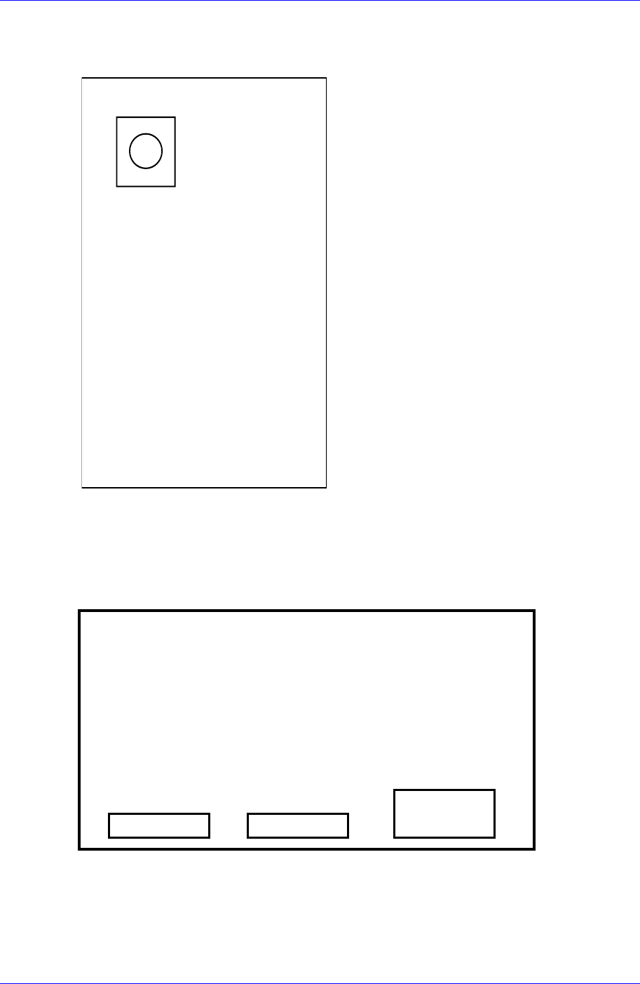
7.8. Conveyor Step Motor Driver(1,600 pulse Fixing)
Model Name : CSMD2-LU340
CN3 CN2 CN1
Figure 7-12. Conveyor Step Motor Driver
7-26

Inspection of the Controller
7.9. Motor troubleshooting
In the following pages, explanations will be provided on the possible causes of each
alarm and malfunction, the investigative methods and taking corrective measures.
7.9.1. Taking Measures at the time of Alarm Occurrence
When an alarm occurs, the 7-segment LED displays an alarm code with blinking. Besides,
it is possible to output the three upper bits (bits 7,6,5) of an alarm code as a general
purpose external output.
When an alarm occurs, in order to resume operation, confirm the contents in 7.9.1.1
Alarm List, rectify the cause first according to the correct measures (7.9.1.2), and ensure
the safety.
7.9.1.1. The List of Alarm and Warning
Indicate alarm and warning. The alarm can be cleared by inputting Alarm Reset (RST).
The alarm “No” in Alarm Clear can not be cleared unless the control power supply is shut
off. The operation at the time of detection “DB” means dynamic brake and “SB” means
deceleration to stop at sequence current limit value. (“-“ is an alarm detected only in
initial processing.) Note that when select dynamic braking as a forced stop function, the
operation at the time of detection certainly becomes dynamic braking.
Table 7-1. Alarm List
Alarm Code
Display Bit7 Bit6 Bit5
Alarm Name Contents
Operation
At
detection
Alarm
Clear
21H
Power module error
(Over-current)
Over current of drive
module
Drive power supply error
Overheat of drive module
DB Yes
22H
Current detection
error 0
Error of current detection
value
DB Yes
23H
Current detection
error 1
Error of current detection
circuit
DB Yes
Drive
24H
0 0 1
Current detection
error 2
Communication error of
current detection circuit
DB Yes
41H Overload 1
Excess effective torque
SB Yes
43H
Regenerative error
Excess regenerative load
ratio
DB Yes
51H
Overheat of amplifier Detecting overheat of
amplifier’s ambient
temperature
SB Yes
53H
Overheat of DB
resistor
Detecting overheat of DB
resistor
SB Yes
54H
Internal overheat
Note 1)
Overheat detection of
Internal regenerative
resistor
DB Yes
Load
55H
0 1 0
External overheat Overheat detection of
Internal regenerative
resistor
DB Yes
7-27