Maintenance Reference(CP45FV) Eng.pdf - 第73页
Inspection of the Contr oller 7-3 LED lit green: The m onitor is operating in normal. LED is blinking The monitor is in power saving mode. Check to see if the monitor cable is connected prop…
Samsung Component Placer CP45FV Series Maintenance Guide
7.2. Inspection of the Controller
7.2.1. Inspection of the Controller Rack
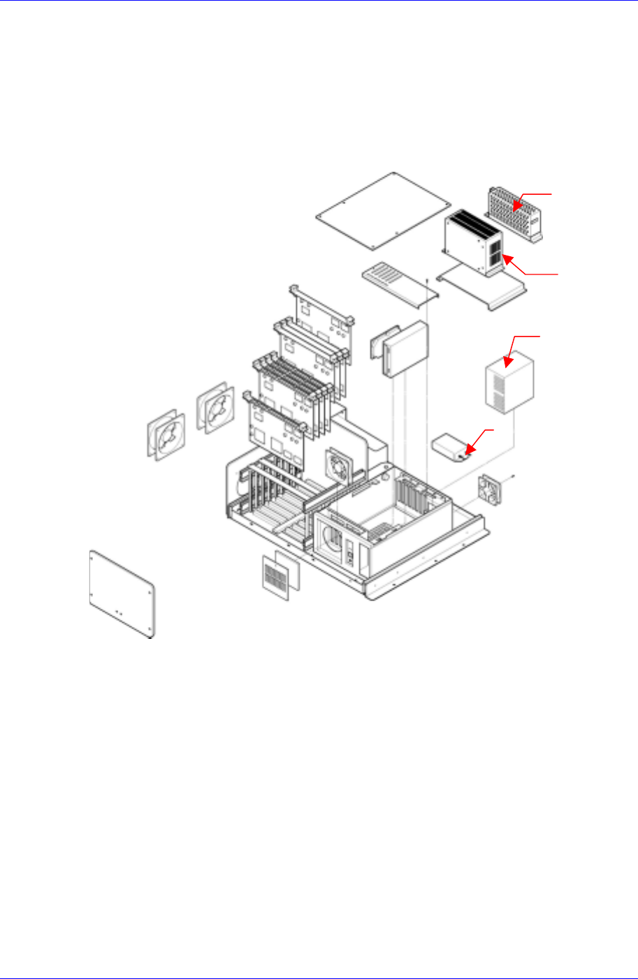
The input power (AC 110V) of the power supply controller is supplied from the output
terminal of the Noise Filter 2 (NF#2) to the PS#1, PS#2. The PS#1, PS#2 are attached to
the Rear Side of the Control Rack. The PS#1 supplies DC 5V and PS#2-1 supplies DC
+12V and DC -12V with VME Backplane and the PC Power Supply supplies DC 5V and
DC +12V with the PC.
N
F#2
PS#2
PS#1
PC P/S
Figure 7-2. Control rack
7.2.2. Inspection of the Rack Part
7.2.2.1. Inspection for PC
① Check to see if the Video card is installed properly.
② Check to see if the HDD cables are connected properly.
③ Check to see if the FDD cables are connected properly.
④ Check to see if the PC ISA I/F boards are assembled properly.
7.2.2.2. Detail Inspection for PC
7.2.2.2.1. Video Card
Check the LED in the lower right side of monitor.
7-2

Inspection of the Controller
7-3
LED lit green: The monitor is operating in normal.
LED is blinking
The monitor is in power saving mode.
Check to see if the monitor cable is connected properly.
Check to see if the Video card is installed properly.
LED is off
Check to see if the power switch of the monitor is on.
Check to see if the power supply cable is connected properly.
Check to see if the power is being supplied.
Check to see if the CP2 is cut off and the power is not supplied, if so turn the
power off and unplug the power cable, and then re-supply the power by using
the CP1.
Check to see if the Video card is installed properly.
7.2.2.2.2. Hard Disk Drive (HDD)
Inspection for the power supply
Check to see if the PC Power module connector is connected properly.
Check to see if the HDD cable is connected properly.
In case of the PC cannot detect the HDD
Check to see if the HDD is set as 'MASTER'.
JP4 □ □
JP3 □ □
JP2 □ □
JP1 □━□
Figure 7-3. HDD Jumper Setting
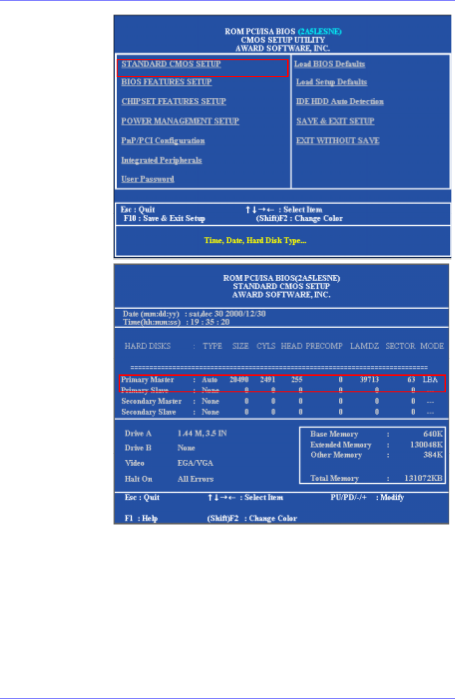
HDD detection
First turn the power on, and then change to CMOS Setup mode by pressing
the <F2> or <Delete> key.
Select the Standard CMOS Setup Menu from the main menu, and then
change the HDD type to 'AUTO' by using <>, <>, <>, <> keys at
the Primary Master.
Samsung Component Placer CP45FV Series Maintenance Guide
Change to the main menu by pressing <Esc> key, and then enter into the
'IDE HDD auto detection'.
Select the 'LBA' from the list.
Change to the main menu by pressing <Esc> key, and then select the 'SAVE
& EXIT Setup' to store current setting.
The PC may detect the HDD after automatic re-booting.
Booting using the FDD
Follow the below procedures in case of the 'IDE HDD auto detection' is not
available.
Select the 'BIOS Features Setup' from the CMOS Setup main menu, and then
7-4