Maintenance Reference(CP45FV) Eng.pdf - 第22页
Samsung Component Placer CP45FV Series Maintenance Refer ence Symbols used in this manual The meaning of symbols used in this manual are as follows: Reference indicates a part to be referred to. Memo shows useful infor…

Preface
ix
About This Manual
Related manuals
Manuals related to this manual are listed below:
Operations manual of this machine.
Overview, Programming Guide
Reference Manual of this machine.
Maintenance Guide, Troubleshooting Guide
Typographical conventions
A number of typographical features and conventions used in this manual.
Text indicated in italics in quotation marks (" ") denotes the title of a manual, or
the title of a chapter or section included in reference. If the title of a section is to
be referred to, the corresponding page number is also shown.
Please refer to "Chapter 1. Menu Structure of MMI" of "Operations Manual".
Please refer to "1.1 MMI of this Machine (page 1-1)".
Characters in quotation marks (" ") denote the title of a dialog box or message
box encountered while operating MMI.
An "open" dialog box is taken as an example.
Characters in angle brackets (< >) denote a button within a dialog box or
message box, or a button or icon to be clicked in the title, keyboard, or teaching
box. When explaining about a dialog box or message box, titles within a box are
shown along with a distinct sign (, , , etc.).
Click <OK> button.
The following texts are entered in the <Code Description>.
Description Code
<OK> button
Characters in brackets([ ]) denote keys to be pressed simultaneously on the
keyboard or in the teaching box. Each key is coupled by a plus (+) sign.
New command [Ctrl + N]

Samsung Component Placer CP45FV Series Maintenance Reference
Symbols used in this manual
The meaning of symbols used in this manual are as follows:
Reference indicates a part to be referred to.
Memo shows useful information related to the text or definition of terms.
Operational procedure
Reference
Memo
The operations procedures for MMI, installation of a teaching box or machine
are described. Each step of procedure is indicated by a number.
x
Preface
xi
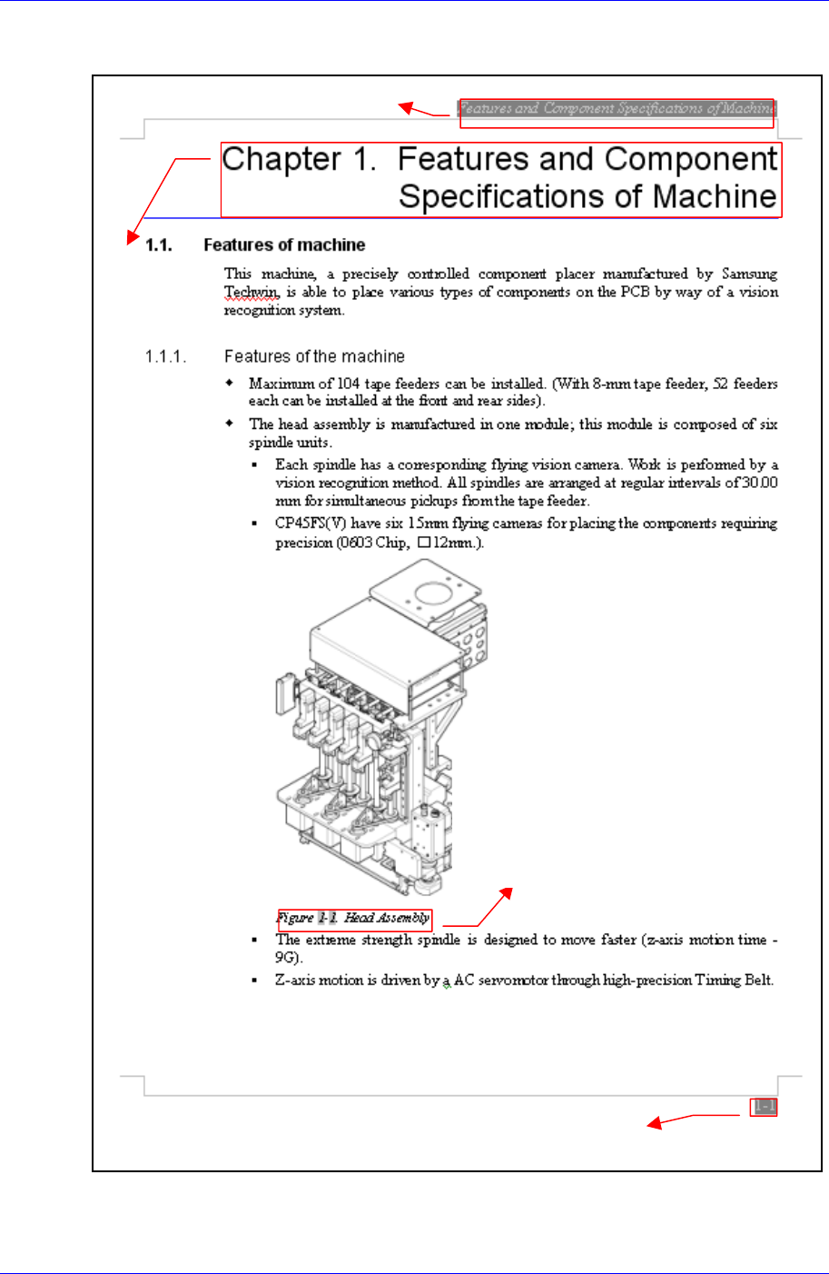
Page Layout
Chapter Title / Manual Name
itle
Figure (Chapter number)-(Serial number) (Title o
f
the figure)
Indicates that this is the first figure o
f
Chapter 1 and that the title of the figure is
Head Assembly
.
Chapter number – page (Indicates the first page of Chapter 1)
Chapter T