Maintenance Reference(CP45FV) Eng.pdf - 第90页
Samsung Component Placer CP45FV Series Maintenance Guide LED information for board status diagnosis LED ON DESCRIPTION REMARK LED ON DESCRIPTION REMARK LED1 Can transmission LED5 IO RESET LED2 Error Occurrence LED6 Boa…
Inspection of the Controller
Description of major functions
INPUT
PIN NO. DEF. DESCRIPTION REMARK
1 CANH
2 CANL
CAN communication signal
Connection with CAN
communication signal of other
nodes
CN2/
CN3
3 /IO-RES RESET Signal FROM CAN MASTER
1 24VP DC+24V for OUTPUT PORT
Apply after inputting the
READY SW
2 24V DC+24V for INPUT PORT
then DC+5V for BOARD is
generated
CN4
3/4 24G DC+24V GROUND -
OUTPUT
PIN NO. DEF. DESCRIPTION REMARK
1/2 +24VPF Power For LED BOARD
3/4 OUT1.0~1.3
HEAD#1 FRONT(STAGE#1 FRONT)
Illumination
5/6 +24VPF Power For LED BOARD
7/8 OUT1.4~1.7
HEAD#2 FRONT(STAGE#1 UPPER)
Illumination
9/10 +24VPF Power For LED BOARD
CN5
11/12 OUT2.0~2.3
HEAD#3 FRONT(STAGE#1 SIDE)
Illumination
12PIN CONNECTOR
1/2 +24VPF Power For LED BOARD
CN6
3/4 OUT2.4~2.7
HEAD#4 FRONT(STAGE#2 FRONT)
Illumination
5/6 +24VPF Power For LED BOARD
7/8 OUT3.0~3.3
HEAD#5 FRONT(STAGE#2 UPPER)
Illumination
9/10 +24VPF Power For LED BOARD
CN6
11/12 OUT3.4~3.7
HEAD#6 FRONT(STAGE#2 SIDE)
Illumination
12PIN CONNECTOR
1/2 +24VPF Power For LED BOARD
3/4 OUT4.0~4.3
HEAD#1 SIDE(STAGE#3 FRONT)
Illumination
5/6 +24VPF Power For LED BOARD
7/8 OUT4.4~4.7
HEAD#2 SIDE(STAGE#3 UPPER)
Illumination
9/10 +24VPF Power For LED BOARD
CN7
11/12 OUT5.0~5.3
HEAD#3 SIDE(STAGE#3 SIDE)
Illumination
12PIN CONNECTOR
1/2 +24VPF Power For LED BOARD
3/4 OUT5.4~5.7
HEAD#1 DIFFUSE(STAGE#4 FRONT)
Illumination
5/6 +24VPF Power For LED BOARD
7/8 OUT6.0~6.3
HEAD#2 DIFFUSE(STAGE#4 UPPER)
Illumination
9/10 +24VPF Power For LED BOARD
CN8
11/12 OUT6.4~6.7
HEAD#3 DIFFUSE(STAGE#4 SIDE)
Illumination
12PIN CONNECTOR
1/2 +24VPF Power For LED BOARD
3/4 OUT7.0~7.3
HEAD#4 DIFFUSE(STAGE#5 FRONT)
Illumination
5/6 +24VPF Power For LED BOARD
7/8 OUT7.4~7.7
HEAD#5 DIFFUSE(STAGE#5 UPPER)
Illumination
9/10 +24VPF Power For LED BOARD
CN9
11/12 OUT8.0~8.3
HEAD#6 DIFFUSE(STAGE#5 SIDE)
Illumination
12PIN CONNECTOR
1 OUT8.4
BACK
Illumination
3 OUT8.5
BACK
Illumination
CN10
5 OUT8.6
BACK
Illumination
6PIN CONNECTOR
7-19

Samsung Component Placer CP45FV Series Maintenance Guide
LED information for board status diagnosis
LED ON DESCRIPTION REMARK LED ON DESCRIPTION REMARK
LED1 Can transmission LED5 IO RESET
LED2 Error Occurrence LED6 Board Output Power
LED3 Can Receiving LED7
Board Operation
Power
LED4 CPU Operation
7.4. Inspection of the Motor Part
7.4.1. X-axis
Check if the power of the motor drive is normal. The LED rotates in the form of
figure '8'.
Check to see if the command connector from the axis board is connected properly.
Check the connector terminal status and connection status of each drive.
Check the status of encoder line and power supply line.
7.4.2. Y-axis
Check if the power of the motor drive is normal. The LED rotates in the form of
figure '8'.
Check to see if the command connector from the axis board is connected properly.
Check the connector terminal status and connection status of each drive.
Check the status of encoder line and power supply line.
7.4.3. Z1~Z6, S, W axis
Check if the power of the motor drive is normal. The LED rotates in the form of
figure '8'.
Check to see if the command connector from the axis board is connected properly.
Check the connector terminal status and connection status of each drive.
Check the status of encoder line and power supply line.
At this time, change the direction of movement manually and check if the sign of the
RPM shown in the LED Display is changed.
7.4.4. R1/2, R3/4, R5/6 axis (THETA1, THETA2, THETA3)
Check the power of the motor drive.
Check to see if the command connector from the axis board is connected properly.
The command connector is connected to the CN2, CN5, CN8 of the STEP I/F board.
Check to see if the R1/2(THETA1), R3/4(THETA2), R5/6(THETA3) from the CN3,
CN6, CN9 of the STEP I/F board is connected properly.
Check the connector terminal status and connection status of each drive.
7-20
Inspection of the Controller
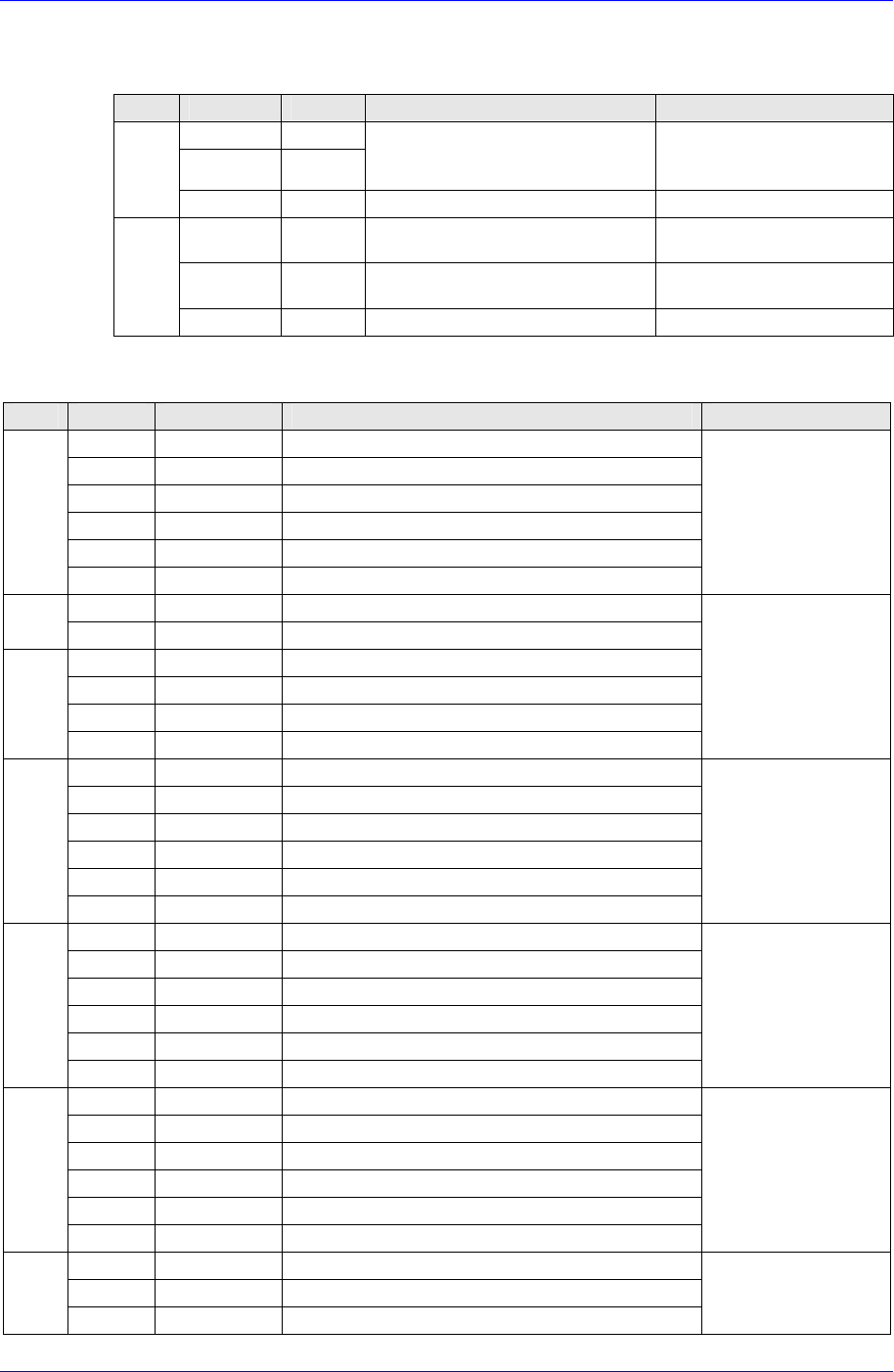
7.5. Board Jumper Setting
J12 : 8 EPROMs = 4MB
21
15 16
J12
Configuration 3 : 512K
×
8EPROMs
J11 : EPROM booting
GPIO0
GPIO1
GPIO2
GPIO3
GPIO4
GPIO5
GPIO6
GPIO7
21
7
15 16
8
J11 User Code Installed
User-Defiinable
User-Defiinable
User-Defiinable
In=Flash; Out=EPROM
User-Defiinable
User-Defiinable
User-Defiinable
User-Defiinable
EPROMs Selected (Factory configuration)
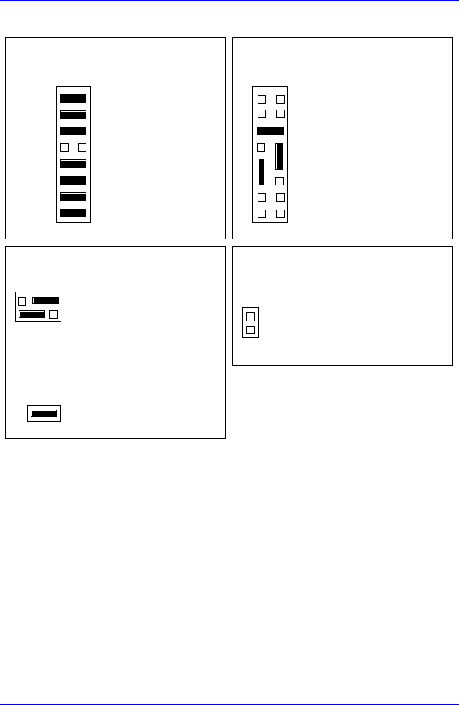
J13 : Primary Source VMEbus +5V STBY
2
1
J13
6
5
Primary Source VMEbus +5V STBY
Secondary Source Onboard Battery
J1 : System Controller
21
J1
System Controller (Factory configuration)
J14 : SCSI terminator disabled
2
1
J14
On-Board SCSI Bus Terminator Disabled
Figure 7-5. MVME162-220 Jumper Setting
7-21