Maintenance Reference(CP45FV) Eng.pdf - 第47页
W eekly Inspection 3-9 Contact the service center to acquire replaceme nt for the belt if an abnormal wear has been found. 3.2.4.2. Belt and Pulley for Adjusting C onveyor Width On Automatic Operation Ins…
Samsung Component Placer CP45FV Series Maintenance Reference
to break it. If the fitting is damaged.
When the blow chamber is not tightened enough, air leak can occur. Tighten it so that
tight fastening can be maintained. At this time, take precautions so that the O-ring for
packing located inside the blow chamber doesn't get dislocated.
When replacing the blow chamber due to abnormal air leakage or damage, contact
our C/S Company for proper instructions.
In case the coil tubes are twisted with each other, untwist the twisted tubes turning the
rotary fitting connected to the housing.
3.2.4. Conveyor System
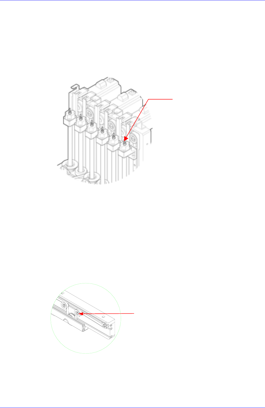
3.2.4.1. PCB Conveyor Belt
Inspection
Check the tension of the belt to see if it is too tight or too loose.
Check the belt for abnormal wear.
Check the driving motor pulley for abnormal wear.
Check the support idler for abnormal wear.
Check the belt to see if it has shifted in position or is coming off.
Support Idler
Rotary
Fitting
Figure 3-6. PCB Conveyor Belt
Solution
Use the support idler for the motor to adjust the tension of the belt if it seems too tight
or too loose.
3-8
Weekly Inspection
3-9
Contact the service center to acquire replacement for the belt if an abnormal wear has
been found.
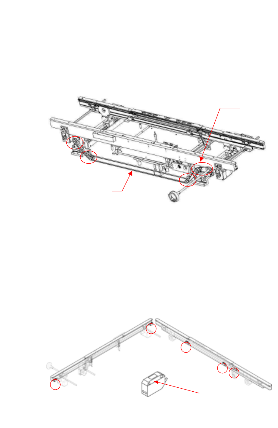
3.2.4.2. Belt and Pulley for Adjusting Conveyor Width On Automatic Operation
Inspection
Check the tension of the belt to see if it is too tight or too loose.
Check the belt for abnormal wear.
Check the pulley for abnormal wear.
Pulley
Belt
Solution
If the tension of the belt is adjusted with the screw for belt tension adjustment, the
motor might be affected. When you need to adjust the tension, please contact our C/S
center immediately for A/S.
3.2.4.3. PCB Detect Sensor
Inspection
Check to see if the sensor window has been contaminated.
Check the sensor's performance to see whether it is functioning or not.
Check the operation of sensor.
Sensor Window
Figure 3-7. PCB Detect Sensor
Solution
Samsung Component Placer CP45FV Series Maintenance Reference
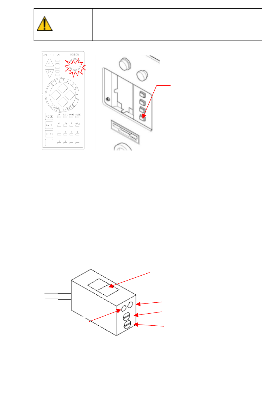
Warning
After clicking the “Motor Free” button on the teaching box,
click the “Stop” and “Reset” buttons on the front operation
panel. Conduct inspection while the motor power supply is
turned off.
FREE
Reset
Button
Eliminate the contamination and clean the sensor window with a soft cloth.
Check the sensitivity of sensor.
The conditions for detection may vary depending on the installation method, distance,
and angle and location of each sensor as well as due to dust, external light, shape, and
color of the board. Therefore, sensitivity of a sensor should be adjusted by using the
actual board that will be used. When adjusting the sensitivity of the board detecting
sensor, if there is no PCB, neither the red nor the green LEDs shall be turned on. The
“lightness/darkness“ adjusting screw shall always be turned to the “L” side.
If there is a PCB, turn the sensitivity adjusting screw clockwise so that both the red
and green LEDs are turned on.
If the “lightness/darkness“ adjusting screw is not turned to the “L” side, only the red
LED is turned on.
For reference, the sensitivity of the input sensor, quick load sensor and output sensor
cannot be adjusted.
Sensor Window
Red LED
Green LED
Sensitivity Control Screw
Lightness/Darkness Adjusting Screw
If the sensor is found defective, contact the service center for a replacement.
3.2.4.4. Stopper (Hard Stop) Inspection
Inspection
Check the upper section of the stopper (or hard stop) to see if excessive wear has
3-10