TR3-GL541-1_1E.pdf.pdf - 第33页
Notes: Chapter 1 1.5 Opening the Inner Cover Edition 1.0 1-10 GL-541E Level 3 Reference

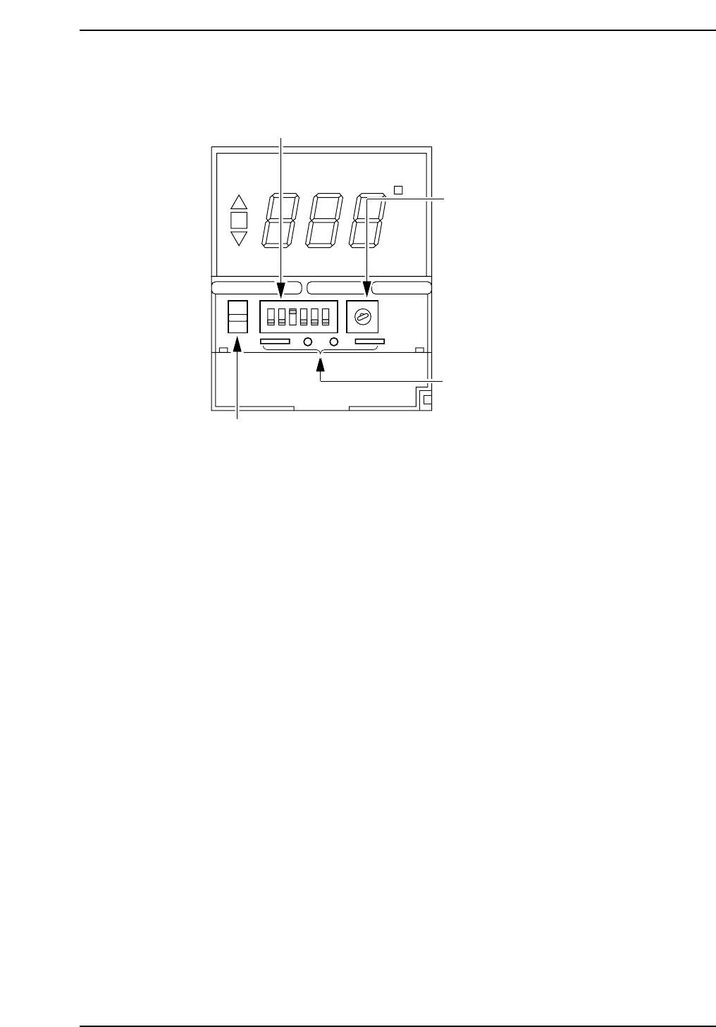
1.5 Opening the Inner Cover
Insert a Phillips screwdriver into the notch in the bottom of the cover and raise it.
ON
°C
AL
SP AL
Phillips
screwdriver
Temperature warning
setup switch
Control mode switch
GL541-m49E
Chapter 1 1.5 Opening the Inner Cover
Edition 1.0 1-9 GL-541E Level 3 Reference

Notes:
Chapter 1 1.5 Opening the Inner Cover
Edition 1.0 1-10 GL-541E Level 3 Reference
1.6 Switches Inside the Inner Panel
1. Control mode dip switches
Do not change the position of these switches. To do so will cause
abnormal operation.
Switch no. and position:
1: OFF, 2: OFF, 3: ON, 4: OFF, 5: OFF, 6: OFF
2. Temperature range setup key
Do not change the position of this key. To do so will cause abnormal
operation.
Position: 2
3. Check terminals
These terminals are used for checking the unit at the factory. Do not
insert anything into these terminals.
4. Protect switch
Set this switch in the up position to prevent changes from being made to
the setup temperature. By setting the protection switch to the up
position, the temperature status switch key can be used to display the
settings as usual. However, the setup keys cannot be used to make
changes to the settings. Use the protect switch to prevent settings from
being accidentally changed.
ON
°C
SP AL
1
4
2
3
ON
12 3
4
56
1
2
3
5
6
4
8
7
9
0
PROTECT
GL541-m08E
1. Control mode dip switches
2. Temperature range setup key
3. Check terminals
4. Protect switch
Chapter 1 1.6 Switches Inside the Inner Panel
Edition 1.0 1-11 GL-541E Level 3 Reference