TR3-GL541-1_1E.pdf.pdf - 第42页
Chapter 2 V ision System

Notes:
Chapter 1 1.9 Connecting the Communication Cable
Edition 1.0 1-18 GL-541E Level 3 Reference

Chapter 2
Vision System
2.1 Vision System
There is one CCD camera located inside the GL-541E machine. This is called the
optical correction camera.
The CCD camera outputs a signal proportional to the detected brightness. This
signal is directly processed by the vision processing card. These values are stored
in the form of a “Pixel Map”, where each pixel (or picture element) is a small part
of the image that is captured by the camera.
2.1.1 Optical Correction Camera
The optical correction camera has three primary functions. The first of these is to read
fiducial marks in order to ascertain the actual position of the board inside the machine,
and so offset board skew, warpage etc. The second function performed by the camera is
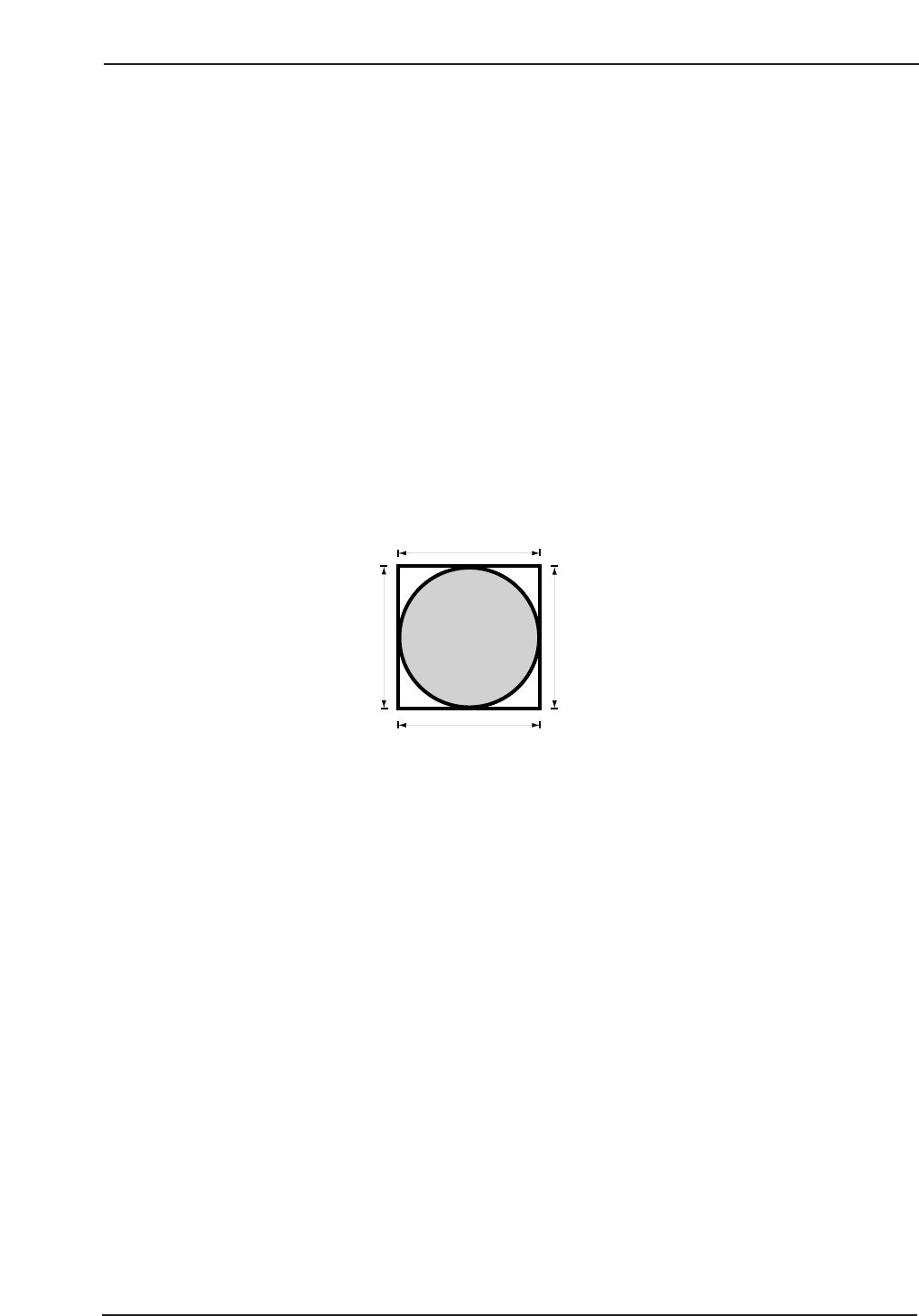
the reading and processing of glue check marks. The camera measures both the glue dot
size (see below) and the dot area. It then compares this data with the reference data
stored in the machine and automatically adjusts air pressure in order to achieve the
desired dispensing results.
The final function performed by the camera is needle offset measurement. The camera
analyses a series of dots dispensed on the needle offset station at 0° and 180°. It then
automatically calculates offsets in the X-, Y-, and Q-axes.
GL541R201
Glue Check Dot size measurement
Chapter 2 2.1 Vision System
Edition 1.1 2-1 GL-541E Level 3 Reference