TR3-GL541-1_1E.pdf.pdf - 第5页
Page Layout Each page indicates the chapter number, section title and number, body, manual name, page number, and the edition number. Chapter number The chapter number to which each section belongs is shown on the header…

About This Manual
This manual contains important machine maintenance information for the user.
The manual content is intended for specialized technicians who are familiar with the
systems used in this machine.
Please read this manual carefully in order to ensure safe and efficient machine
maintenance.
Some of the machine names used in this manual are not the formal machine names.
(Formal machine name) (Notation used in this manual)
FUJI GL-541E GL-541E
Manual Structure
This manual consists of the following four chapters.
Safety Guidelines
Chapter 1 Setup
Chapter 2 Vision System
Chapter 3 Proper Data
About This Manual
Edition 1.1 i GL-541E Level 3 Reference
Page Layout
Each page indicates the chapter number, section title and number, body, manual name,
page number, and the edition number.
Chapter number
The chapter number to which each section belongs is shown on the header on each page.
The manual is made up of four chapters as detailed earlier in this section.
Section number and title
The title of each chapter is shown in the header on each page. Each part may contain one
or more sections.
Section title
Each chapter may be divided into several sections. The section number is composed of
the number of the chapter to which the section belongs, followed by a sequential number
for each section.
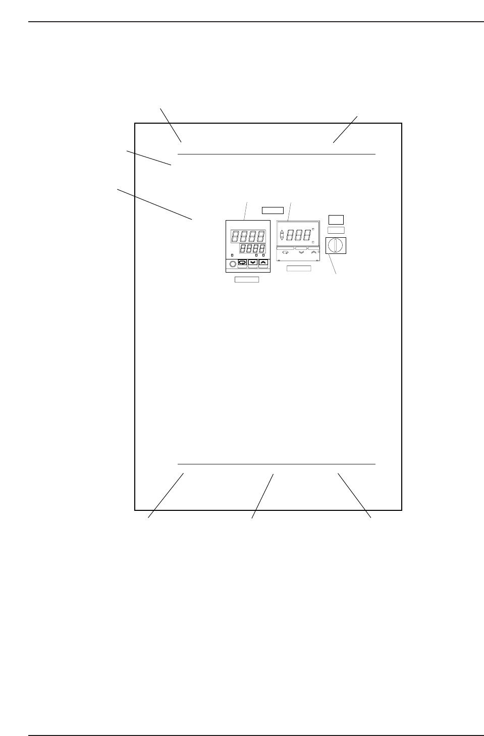
1.1 Temperature Control Unit
Operation Panel
1. Temperature regulator (Main)
Input the temperature under which the glue is used. This regulator
controls the current which is sent to the heater so that the temperature
reaches the set value. This regulator is used to adjust the heater
temperature.
2. Temperature regulator (for cooler unit)
Input the temperature under which the glue is used. This regulator
switches the air flow to the cooler when the supplied air temperature is
higher than the setup value.
3. Thermostat power switch
Normally, when the power to the machine is switched on, the thermostat
power switch should be ON. However, be sure to set the thermostat
power switch to OFF when the machine is in pass mode.
OUT
°C
PV
SV
ALM1 ALM2
omRon
E5CJ
ON
°C
AL
SP AL
OMRON E5CS
COOLER ON
TEMP ADJ.
POWER ON
THERMOSTAT
THERMOSTAT
ON OFF
1
2
3
1. Temperature regulator
2. Temperature regulator (for starting cooler)
3. Power switch
GL541-m60E
Chapter 1 1.1 Temperature Control Unit
Edition 1.1 1-1 GL-541E Level 3 Reference
Chapter number
Section number and title
Section title
Body
Edition number
Page number
Manual name
GL541TC1
About This Manual
Edition 1.1 ii GL-541E Level 3 Reference

Body
The information needed to understand the workings of the machine and how to perform
operation is explained using text and illustrations.
Page number
A two digit hyphenated number appears in the footer on each page. The first digit of
each page number indicates the chapter number and the second digit is the sequential
page number within that chapter. Page 1-2, for example, indicates that this is the second
page in the first chapter.
Manual name
The name of the manual that appears on the cover is also shown in the footer on each
page.
Edition number
The edition number is updated each time the manual is revised, with the number
reflecting the scale of changes that were made.
Minor revision: Minor changes are reflected in the part of the edition number after
the decimal point, for example, a change from edition 1.0 to 1.1. This
change is made on the revised pages only, and these pages can be
downloaded as required from Fuji's website.
Major revision: If major changes are made, the edition number is increased by one,
for example, a change from edition 1.0 to 2.0. This change is made on
all pages, including the cover.
Notation Conventions Used in this Manual
The notation conventions employed in this manual are described below.
[Production] command The names of the command buttons are enclosed in brackets,
and use the verb “press”.
START button Buttons on the machine are written exactly as they appear,
and use the verb “press”.
“Production” command section The names of commands that have been grouped
together are enclosed in quotation marks.
[TAB] key Keys on the keyboard appear in brackets.
About This Manual
Edition 1.1 iii GL-541E Level 3 Reference