TR3-GL541-1_1E.pdf.pdf - 第35页
Notes: Chapter 1 1.6 Switches Inside the Inner Panel Edition 1.0 1-12 GL-541E Level 3 Reference
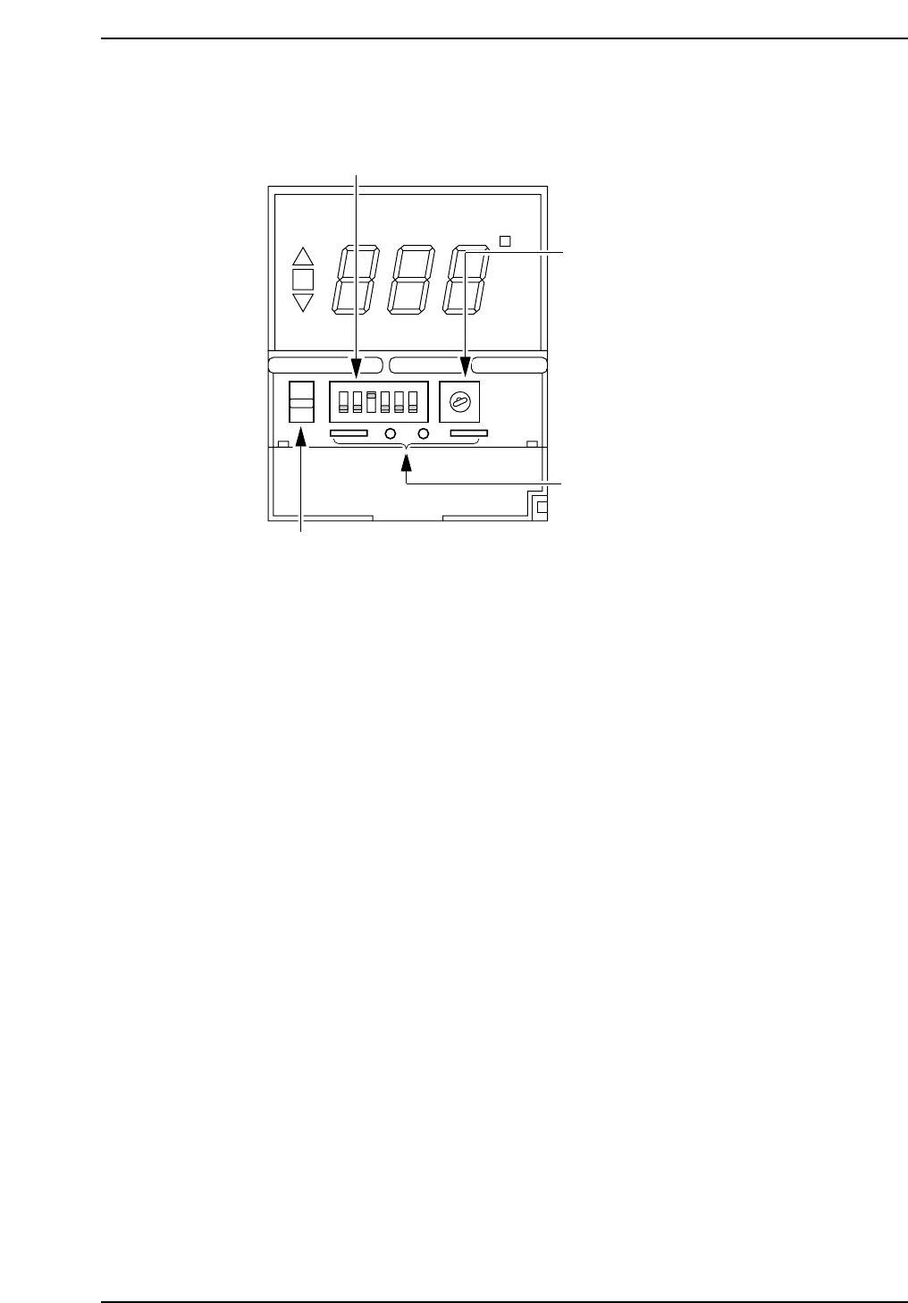
1.6 Switches Inside the Inner Panel
1. Control mode dip switches
Do not change the position of these switches. To do so will cause
abnormal operation.
Switch no. and position:
1: OFF, 2: OFF, 3: ON, 4: OFF, 5: OFF, 6: OFF
2. Temperature range setup key
Do not change the position of this key. To do so will cause abnormal
operation.
Position: 2
3. Check terminals
These terminals are used for checking the unit at the factory. Do not
insert anything into these terminals.
4. Protect switch
Set this switch in the up position to prevent changes from being made to
the setup temperature. By setting the protection switch to the up
position, the temperature status switch key can be used to display the
settings as usual. However, the setup keys cannot be used to make
changes to the settings. Use the protect switch to prevent settings from
being accidentally changed.
ON
°C
SP AL
1
4
2
3
ON
12 3
4
56
1
2
3
5
6
4
8
7
9
0
PROTECT
GL541-m08E
1. Control mode dip switches
2. Temperature range setup key
3. Check terminals
4. Protect switch
Chapter 1 1.6 Switches Inside the Inner Panel
Edition 1.0 1-11 GL-541E Level 3 Reference

Notes:
Chapter 1 1.6 Switches Inside the Inner Panel
Edition 1.0 1-12 GL-541E Level 3 Reference
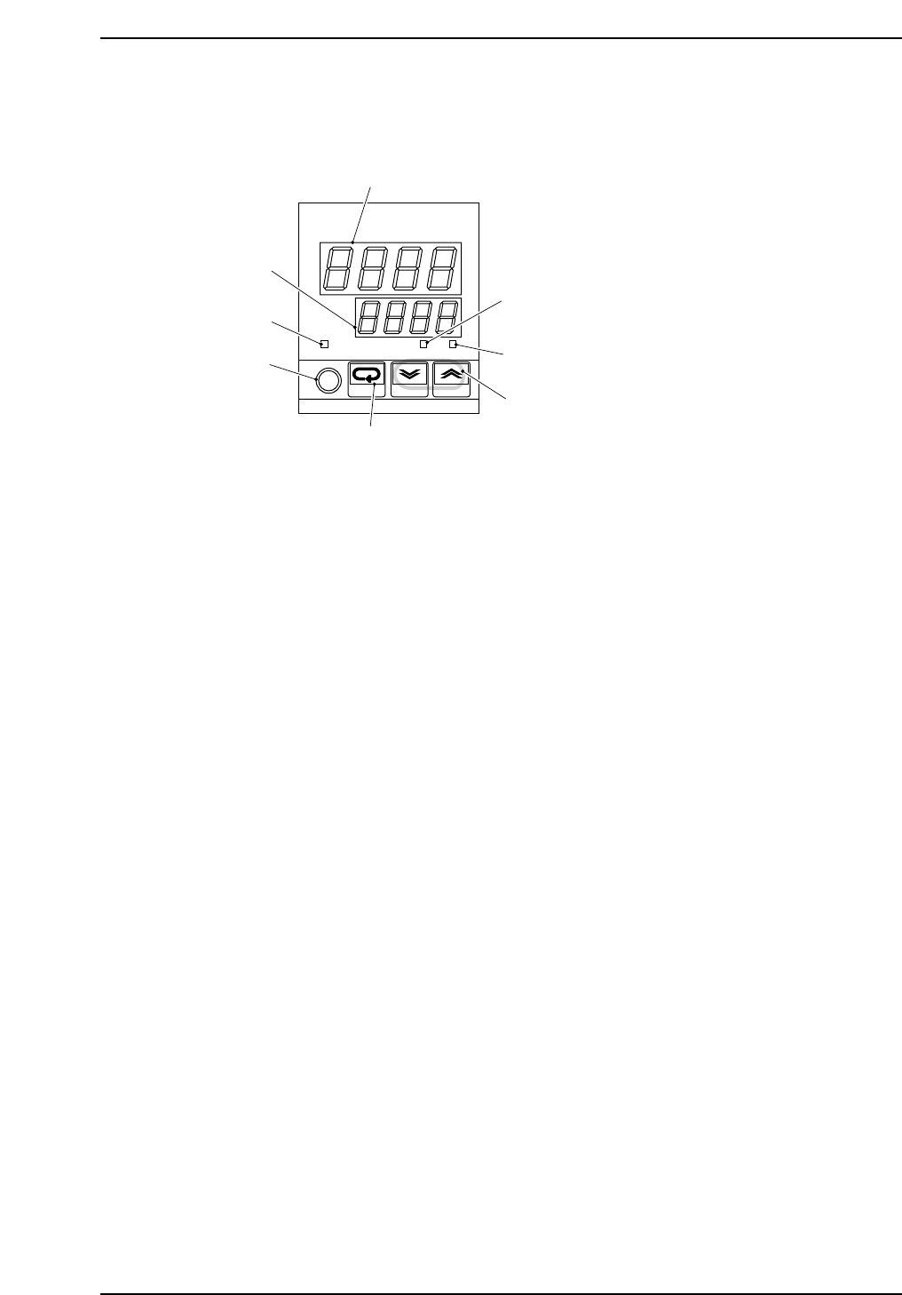
1.7 Temperature Regulator Setup (Main)
Changes can be made to the setup temperature by pressing the setup keys.
Procedure:
1. Hold down the relevant setup key (up or down) until the desired
temperature is reached.
Note:
1. During normal operation the same temperature has to be specified at both temperature
regulators (the main temperature regulator and the temperature regulator for the cooler).
If the specified temperatures differ, the temperature regulators will not function properly.
2. When the machine is to operate at room temperature, the temperature at the regulator for
the cooler should be lowered by three degrees. Thus the temperature is adjusted properly.
Example: To achieve a gluing temperature of 26° at the same room temperature, set the
main temperature regulator to 26° and the cooler temperature regulator to 23°.
OUT
°C
PV
SV
ALM1 ALM2
omRon
E5CJ
1
2
3
4
5
6
7
8
GL541-m59E
1. Temperature display
2. #1 warning lamp
3. #2 warning lamp
4. Setup key (up /down)
5. Mode key
6. Level key
7. Output operation display lamp
8. Setup display
Chapter 1 1.7 Temperature Regulator Setup (Main)
Edition 1.0 1-13 GL-541E Level 3 Reference