Detailed Circuit Diagrams Folder.pdf - 第12页
Sheet Size DIN A2 electric_schematic_TX electric_schematic_TX electric_schematic_TX electric_schematic_TX 90012154-010301LE3 Replaced by Overview Overview Overview Overview Graphics_Connector_MGCU1 & 2 Graphics_Conne…
Sheet
Size DIN A2
electric_schematic_TX
electric_schematic_TX
electric_schematic_TX
electric_schematic_TX
90012154-010301LE3
Replaced by
Machine label
Machine label
Machine label
Machine label
Low Voltage Fuse & Distribution
Low Voltage Fuse & Distribution
Low Voltage Fuse & Distribution
Low V
oltage Fuse & Distribution
Replaced by
5
Weitergabe sowie Vervielfältigung dieser Unterlage, Verwertung und
Mitteilung des Inhalts nicht gestattet, soweit nicht ausdrücklich zugestanden.
Proprietary Data, company confidential.
All rights reserved
Copying of this document, giving it to others and the use or
communication of the contents thereof, are forbidden without express authority.
Doc. No.
Privileged business information.
Do not release
Offenders are liable to payment of damages. All rights are reserved in the
event of the grant or the registration of a utility model or design.
Zuwiederhandlungen verpflichten zu Schadenersatz. Alle Rechte vorbehalten,
insbesondere für den Fall der Patenterteilung oder GM-Eintragung vorbehalten.
Page:
Function: Overview Graphics
==OVGR=TX+ELS/5
drawing number:
03128176-020101GE4
overview_graphics
o
v
erview_gr
aphics
o
v
erview_graphics
overview_graphics
GmbH & Co KG
ASM
Assembly Systems
Copyright reserved
Ed.
Original
Pingist
Date
Date
Modification
Appr
01.12.2016
Name
Version: Series from
V
ersion: S
eries f
r
om
V
ersion: Series from
Version: Series from
2016/Q4 TA500
2016/Q4 TA500
2016/Q4 TA500
2016/Q4 TA500
starting MC-Nr
.: TA500 2016/Q4 G. Pingist
Low voltage distribution board TX
Low voltage distribution board TX
Low voltage distribution board TX
Low voltage distribution board TX
Risk of fire and electric shock!
Risk of fire and electric shock!
Risk of fire and electric shock!
Risk of fire and electric shock!
Replace fuses by specified service parts only!
Replace fuses by specified service parts only!
Replace fuses by specified service parts only!
Replace fuses by specified service parts only!
!
safety controlled voltage >
safety controlled voltage >
safety controlled voltage >
safety controlled voltage >
Indicator near fuse will light red if fuse is blown or safety controlled voltage is off
Indicator near fuse will light red if fuse is blown or safety controlled voltage is off
Indicator near fuse will light red if fuse is blown or safety controlled voltage is off
Indicator near fuse will light red if fuse is blown or safety controlled voltage is off
S
S
S
S
S
S
S
S
F1
F2
F3
F4
F5
F6
F7
F8
F9
F10
F11
F12
F13
F14
F15
F16
F19
F20
F21
F22
F23
MGCU1
MGCU2
Service
Distributor/POWER_FAIL
PC
PC option
Conveyor control
Gantry 1
Gantry 2
internal; Power fail
SSK-ready CSB
CSB supply
internal; electronis supply
Head supply 1
Head supply 2
Conveyor drives
Head Axis 1
Head Axis 2
Vision
FCU1
FCU2
6.3 A
6.3 A
6.3 A
6.3 A
6.3 A
6.3 A
6.3 A
6.3 A
6.3 A
0.5A
6.3 A
6.3 A
3 A
6.3 A
6.3 A
10 A
6.3 A
6.3 A
6.3 A
10 A
10 A
24V
24V
24V
24V
24V
24V
24V
24V
24V
24V
24V
24V
24V
25.5V
25.5V
42V
160V
160V
42V
27V
27V
Fuse No. protects
Current Voltage
S
S
S
S
X25
X25
X25
X25
X26
X26
X26
X26
V2
V2
V2
V2
XB8A
XB8A
XB8A
XB8A
XB8B
XB8B
XB8B
XB8B
X24B
X24B
X24B
X24B
X24A
X24A
X24A
X24A
F3
F3
F3
F3
F2
F2
F2
F2
F1
F1
F1
F1
F8
F8
F8
F8
F22
F22
F22
F22
F4
F4
F4
F4
F11
F11
F11
F11
F12
F12
F12
F12
F7
F7
F7
F7
F20
F20
F20
F20
F19
F19
F19
F19
F23
F23
F23
F23
F9
F9
F9
F9
F6
F6
F6
F6
F5
F5
F5
F5
F16
F16
F16
F16
F15
F15
F15
F15
F21
F21
F21
F21
F14
F14
F14
F14
C26
C26
C26
C26 C2
C2
C2
C2
(Power in 42V)
(Power in 42V)
(Power in 42V)
(Power in 42V)
(Power in 27V, 24V)
(Power in 27V, 24V)
(Power in 27V, 24V)
(Power in 27V, 24V)
(Head Axis 2)
(Head Axis 2)
(Head Axis 2)
(Head Axis 2)
(Head Axis 1)
(Head Axis 1)
(Head Axis 1)
(Head Axis 1)
(PE)
(PE)
(PE)
(PE)
(CSB 160V in)
(CSB 160V in)
(CSB 160V in)
(CSB 160V in)
(CSB control)
(CSB control)
(CSB control)
(CSB control)
X1
X1
X1
X1
C120
C120
C120
C120 C121
C121
C121
C121 C110
C110
C110
C110 C109
C109
C109
C109
C108
C108
C108
C108 C107
C107
C107
C107 C106
C106
C106
C106 C105
C105
C105
C105
C104
C104
C104
C104 C103
C103
C103
C103 C102
C102
C102
C102 C101
C101
C101
C101
X5
X5
X5
X5
X13
X13
X13
X13
X11
X11
X11
X11
X14
X14
X14
X14
X12
X12
X12
X12
X10
X10
X10
X10
X9
X9
X9
X9 S2
S2
S2
S2
RFU
RFU
RFU
RFU
P_OK_PS3_4
P_OK_PS3_4
P_OK_PS3_4
P_OK_PS3_4
P_OK_PS2
P_OK_PS2
P_OK_PS2
P_OK_PS2
SSK_READY
SSK_READY
SSK_READY
S
SK_READY
PWR_ENABLE
PWR_ENABLE
PWR_ENABLE
PWR_ENABLE
S1-K2-OK
S1-K2-OK
S1-K2-OK
S1-K2-OK
S1-K1-OK
S1-K1-OK
S1-K1-OK
S1-K1-OK
POWER-OK
POWER-OK
POWER-OK
POWER-OK
(FCU)
(FCU)
(FCU)
(FCU)
(Trailing
(Trailing
(Trailing
(Trailing
interface 1)
interface 1)
interface 1)
interface 1)
(Trailing
(Trailing
(Trailing
(Trailing
interface 2)
interface 2)
interface 2)
interface 2)
(MGCU supply)
(MGCU supply)
(MGCU supply)
(MGCU supply)
(Conveyor)
(Conveyor)
(Conveyor)
(Conveyor)
(Distributor)
(Distributor)
(Distributor)
(Distributor)
(PC1+Mon.)
(PC1+Mon.)
(PC1+Mon.)
(PC1+Mon.)
PC1 ON
PC1 ON
PC1 ON
PC1 ON
F10
F10
F10
F10
F13
F13
F13
F13
X3
X3
X3
X3
X2
X2
X2
X2
Diagnostic unit
Diagnostic unit
Diagnostic unit
Diagnostic unit
U80: Controller
U80: Controller
U80: Controller
U80: Controller
X3: Prog interface
X3: Prog interface
X3: Prog interface
X3: Prog interface
X2: Comm. interface
X2: Comm. interface
X2: Comm. interface
X2: Comm. interface
DC/DC converter
DC/DC converter
DC/DC converter
DC/DC converter
42->25.5V
42->25.5V
42->25.5V
42->25.5V
Head supply 1
Head supply 1
Head supply 1
Head supply 1
DC/DC converter
DC/DC converter
DC/DC converter
DC/DC converter
42->25.5V
42->25.5V
42->25.5V
42->25.5V
Head supply 2
Head supply 2
Head supply 2
Head supply 2
(Diagnostic
(Diagnostic
(Diagnostic
(Diagnostic
communication)
communication)
communication)
communication)
U80
U80
U80
U80
X8
X8
X8
X8
(Stat Cam)
(Stat Cam)
(Stat Cam)
(Stat Cam)
S
S
S
S
F10 = 0.5A / 24V; Polyfuse. Replace board if defective
F10 = 0.5A / 24V; Polyfuse. Replace board if defective
F10 = 0.5A / 24V; Polyfuse. Replace board if defective
F10 = 0.5A / 24V; Polyfuse. Replace board if defective
F13 = 3A / 24V; SMD fuse. Replace board if blown
F13 = 3A / 24V; SMD fuse. Replace board if blown
F13 = 3A / 24V; SMD fuse. Replace board if blown
F13 = 3A / 24V; SMD fuse. Replace board if blown
F14 / F15 = 6,3A / 42V; (42V converted to 25.5V)
F14 / F15 = 6,3A / 42V; (42V converted to 25.5V)
F14 / F15 = 6,3A / 42V; (42V converted to 25.5V)
F14 / F15 = 6,3A / 42V; (42V converted to 25.5V)
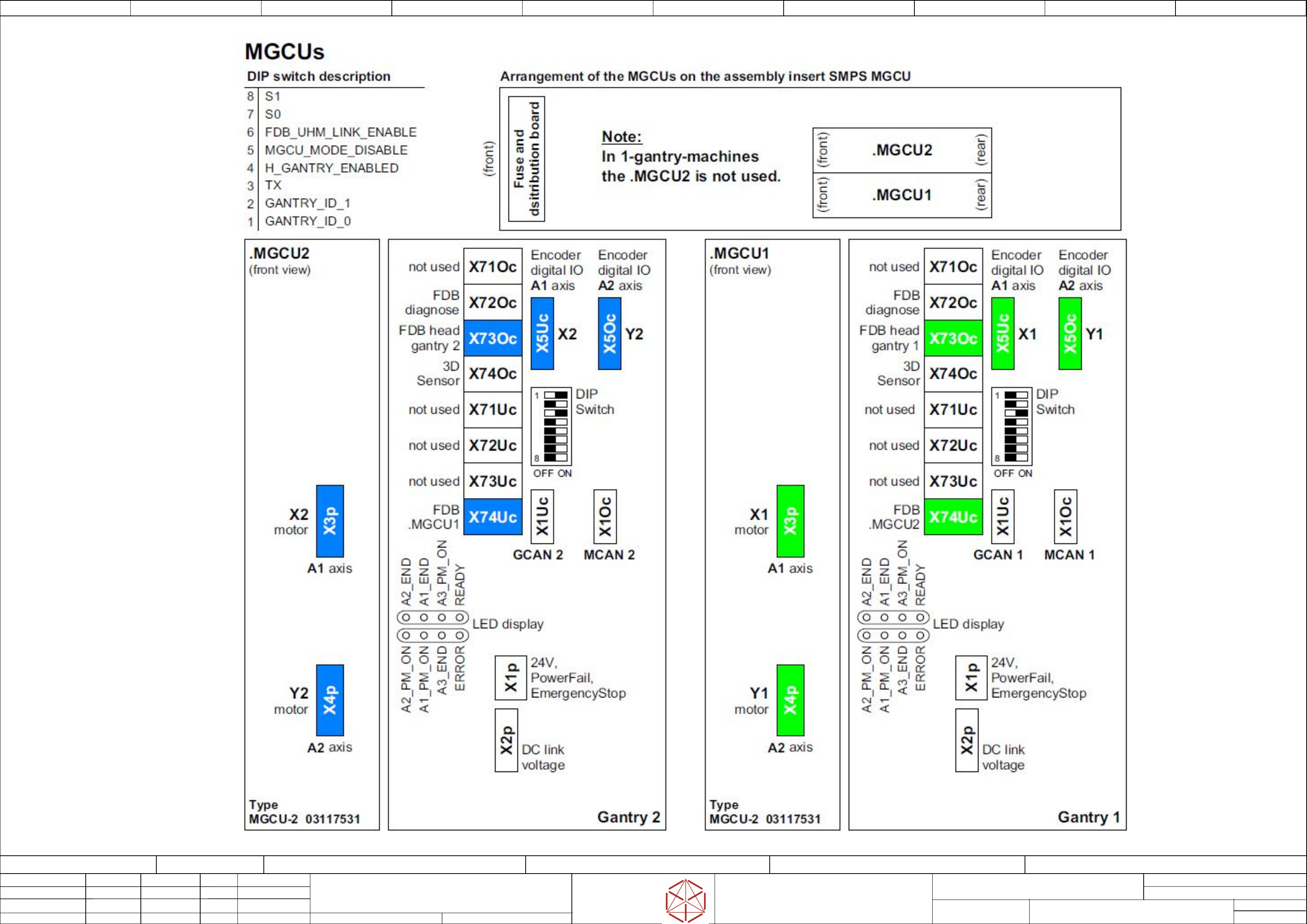
Note:
Note:
Note:
Note:
Sheet
Size DIN A2
electric_schematic_TX
electric_schematic_TX
electric_schematic_TX
electric_schematic_TX
90012154-010301LE3
Replaced by
Overview
Overview
Overview
Overview
Graphics_Connector_MGCU1 & 2
Graphics_Connector_MGCU1 & 2
Graphics_Connector_MGCU1 & 2
Graphics_Connector_MGCU1 & 2
Replaced b
y
6
Weitergabe sowie Vervielfältigung dieser Unterlage, Verwertung und
Mitteilung des Inhalts nicht gestattet, soweit nicht ausdrücklich zugestanden.
Proprietary Data, company confidential.
All rights reserved
Copying of this document, giving it to others and the use or
communication of the contents thereof, are forbidden without express authority.
Doc. No.
Privileged business information.
Do not release
Offenders are liable to payment of damages. All rights are reserved in the
event of the grant or the registration of a utility model or design.
Zuwiederhandlungen verpflichten zu Schadenersatz. Alle Rechte vorbehalten,
insbesondere für den Fall der Patenterteilung oder GM-Eintragung vorbehalten.
Page:
Function: Overview Graphics
==OVGR=TX+ELS/6
drawing number:
03119265-010601LE3
overview_graphics
o
v
erview_gr
aphics
o
v
erview_graphics
overview_graphics
GmbH & Co KG
ASM
Assembly Systems
Copyright reserved
Ed.
Original
Pingist
Date
Date
Modification
Appr
01.12.2016
Name
Version: Series from
V
ersion: S
eries f
r
om
V
ersion: Series from
Version: Series from
2016/Q4 TA500
2016/Q4 TA500
2016/Q4 TA500
2016/Q4 TA500
starting MC-Nr
.: TA500 2016/Q4 G. Pingist
Sheet
Size DIN A2
electric_schematic_TX
electric_schematic_TX
electric_schematic_TX
electric_schematic_TX
90012154-010301LE3
Replaced by
Overview
Overview
Overview
Overview
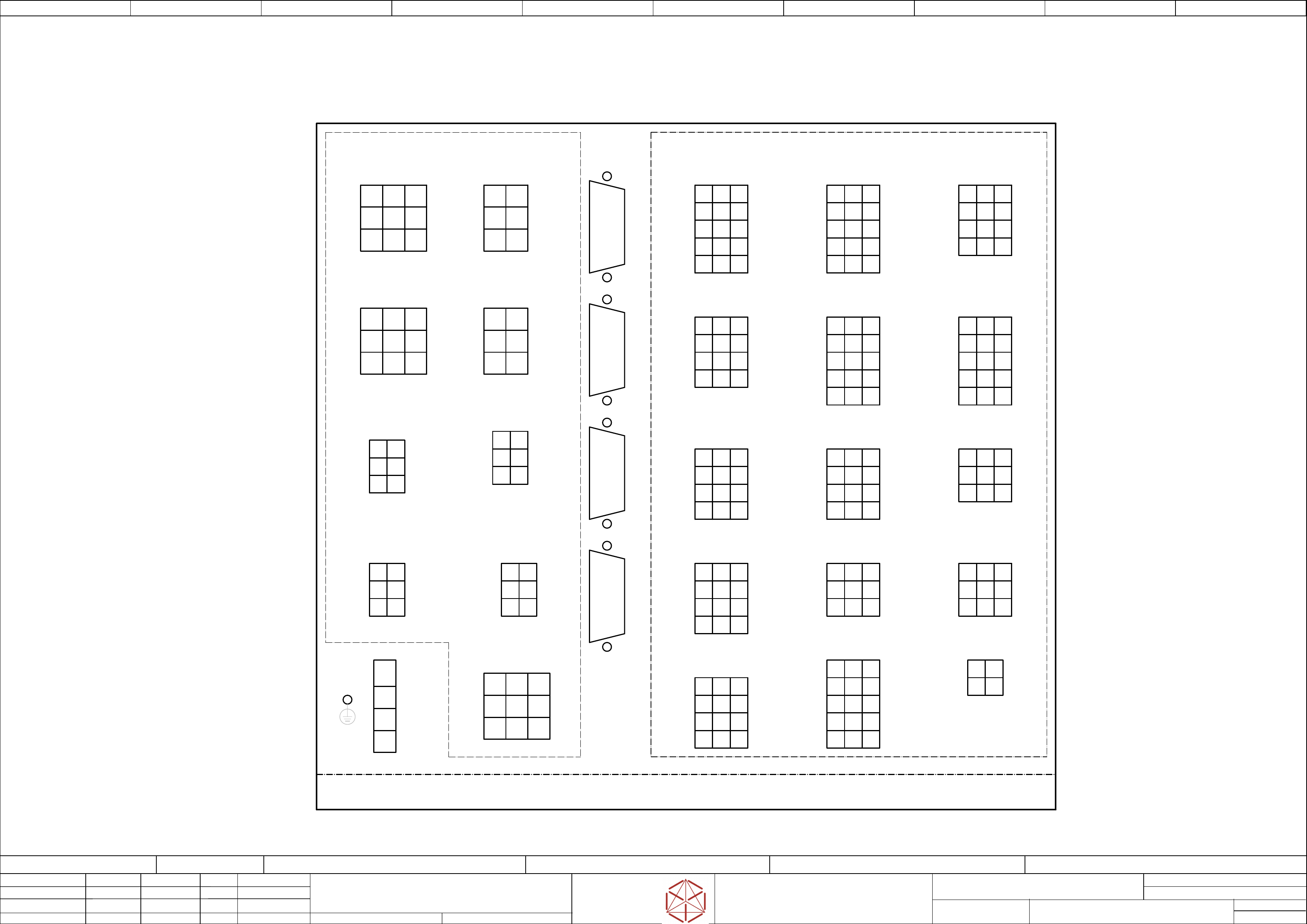
Graphics_Connector_Panel slide_in
Graphics_Connector_Panel slide_in
Graphics_Connector_P
anel slide_in
Graphics_Connector_Panel slide_in
Replaced by
7
Weitergabe sowie Vervielfältigung dieser Unterlage, Verwertung und
Mitteilung des Inhalts nicht gestattet, soweit nicht ausdrücklich zugestanden.
Proprietary Data, company confidential.
All rights reserved
Copying of this document, giving it to others and the use or
communication of the contents thereof, are forbidden without express authority.
Doc. No.
Privileged business information.
Do not release
Offenders are liable to payment of damages. All rights are reserved in the
event of the grant or the registration of a utility model or design.
Zuwiederhandlungen verpflichten zu Schadenersatz. Alle Rechte vorbehalten,
insbesondere für den Fall der Patenterteilung oder GM-Eintragung vorbehalten.
Page:
Function: Overview Graphics
==OVGR=TX+ELS/7
drawing number:
03119265-010601LE3
overview_graphics
o
v
erview_gr
aphics
o
v
erview_graphics
overview_graphics
GmbH & Co KG
ASM
Assembly Systems
Copyright reserved
Ed.
Original
Pingist
Date
Date
Modification
Appr
01.12.2016
Name
Version: Series from
V
ersion: S
eries f
r
om
V
ersion: Series from
Version: Series from
2016/Q4 TA500
2016/Q4 TA500
2016/Q4 TA500
2016/Q4 TA500
starting MC-Nr
.: TA500 2016/Q4 G. Pingist
-X26
-X26
-X26
-X26
Control elements Hood 1
Contr
ol elements Hood 1
Contr
ol elements Hood 1
Control elements Hood 1
-X23
-X23
-X23
-X23
Control elements 1
Contr
ol elements 1
Control elements 1
Control elements 1
-X28
-X28
-X28
-X28
COT
-insert 1
CO
T-insert 1
COT-insert 1
CO
T-insert 1
Signaling & Safety
Signal
ing & Safety
Signaling & Saf
ety
Signaling & Safety
-X27
-X27
-X27
-X27
Control elements Hood 2
Contr
ol elements Hood 2
Contr
ol elements Hood 2
Control elements Hood 2
-X29
-X29
-X29
-X29
COT
-insert 2
CO
T-insert 2
COT-insert 2
CO
T-insert 2
Signaling & Safety
Signal
ing & Safety
Signaling & Saf
ety
Signaling & Safety
-X30
-X30
-X30
-X30
Control V
accum_Pump
Contr
ol Vaccum_Pump
Control V
accum_Pump
Control Vaccum_Pump
Control Interior light
Contr
ol Interior light
Control I
nterior light
Control Interior light
-X31
-
X31
-
X31
-
X31
Pneumatic_Main_S
ystem
Pneumatic_Main_S
ystem
Pneumatic_Main_S
ystem
Pneumatic_Main_System
-X33
-
X33
-
X33
-
X33
Contr
ol V
accum_Pump
Contr
ol Vaccum_Pump
Control V
accum_Pump
Control Vaccum_Pump
Control Interior light
Contr
ol Interior light
Control I
nterior light
Control Interior light
-X32
-
X32
-
X32
-
X32
F
aul
t indicator lamp
F
ault indicator lamp
Fault indicator lamp
F
ault indicator lamp
-X34
-
X34
-
X34
-
X34
F
an contr
ol &
F
an control &
Fan control &
F
an control &
monitoring 1
moni
toring 1
monitoring 1
monitoring 1
-X35
-
X35
-
X35
-
X35
F
an contr
ol &
F
an control &
Fan control &
F
an control &
monitoring 2
moni
toring 2
monitoring 2
monitoring 2
-X36
-X36
-X36
-X36
Securi
ty Loop Flap
S
ecurity Loop Flap
Securi
ty Loop Flap
Security Loop Flap
Ex.Conveyor
Ex.Con
veyor
Ex.Conv
eyor
Ex.Conveyor
-X37
-X37
-X37
-X37
Reserv
e-I/O &
R
eserve-I/O &
Reserv
e-I/O &
Reserve-I/O &
K3-Connection
K3-Connection
K3-Connection
K3-Connection
-X19
-
X19
-
X19
-
X19
RS485 FU
RS485 FU
RS485 FU
RS485 FU
-CAN1
-CAN1
-CAN1
-CAN1
Sub_D 9pol.
Sub_D 9pol.
Sub_D 9pol.
Sub_D 9pol.
-CAN2
-CAN2
-CAN2
-CAN2
Sub_D 9pol.
Sub_D 9pol.
Sub_D 9pol.
Sub_D 9pol.
-CAN3
-CAN3
-CAN3
-CAN3
Sub_D 9pol.
Sub_D 9pol.
Sub_D 9pol.
Sub_D 9pol.
-X5
-X5
-X5
-X5
FCU 1&2 DC 27V
FCU 1&2 DC 27V
FCU 1&2 DC 27V
FCU 1&2 DC 27V
-X102
-X102
-X102
-X102
AC 400V Power_supply
AC 400V P
ower_supply
AC 400V Power_supply
AC 400V Power_supply
PE M5
PE M5
PE M5
PE M5
Mini-Mate.-N-Look 15pol
Mini-Mate.-N-Look 12pol
Mini-Mate.-N-Look 12pol
Mini-Mate.-N-Look 15pol
Mini-Mate.-N-Look 15pol
Mini-Mate.-N-Look 12pol
Mini-Mate.-N-Look 12pol
Mini-Mate.-N-Look 9pol
Mini-Mate.-N-Look 12pol
Mini-Mate.-N-Look 9pol
Mini-Mate.-N-Look 9pol
Mini-Mate.-N-Look 12pol
Mini-Mate.-N-Look 15pol
Mini-Mate.-N-Look 4pol
Mate.-N-Look 9pol
Mate.-N-Look 4pol
-- FDC --
-- FDC --
-- FDC --
-- FDC -- -- DIC --
-- DIC --
-- DIC --
-- DIC --
Fuse & Distribution Connector_field
Fuse & Distribution Connector_field
Fuse & Distribution Connector_field
Fuse & Distribution Connector_field Distributor Connector_field
Distributor Connector_field
Distributor Connector_field
Distributor Connector_field
ELS
ELS
ELS
ELS
-- Connector_Field Electric_slide_in ---
-- Connector_Field Electric_slide_in ---
-- Connector_Field Electric_slide_in ---
-- Connector_Field Electric_slide_in ---
ELS
ELS
ELS
ELS
-CAN4
-CAN4
-CAN4
-CAN4
Sub_D 9pol.
Sub_D 9pol.
Sub_D 9pol.
Sub_D 9pol.
Mini-Mate.-N-Look 15pol
-X24
-X24
-X24
-X24
Control elements 2
Contr
ol elements 2
Control elements 2
Control elements 2
-X8
-X8
-X8
-X8
DC 24/48V
DC 24/48V
DC 24/48V
DC 24/48V
IC & FC-Camer
a
IC & FC
-Camera
IC & FC-Camera
IC & FC
-Camera
Mini-Mate.-N-Look 6pol
-X8A
-
X8A
-
X8A
-
X8A
T
r
ailing interface 1
T
railing interf
ace 1
Trailing interface 1
Trailing interface 1
& 160V
& 160V
& 160V
& 160V
Mate.-N-Look 6pol
-X14
-X14
-X14
-X14
Conv
eyor
Con
veyor
Conv
eyor
Conveyor
Mate.-N-Look 9pol
-X9
-X9
-X9
-X9
DC 24V PC1 & Monitor
DC 24V PC1 & Moni
tor
DC 24V PC1 & Moni
tor
DC 24V PC1 & Monitor
Mini-Mate.-N-Look 6pol
-X8B
-X8B
-X8B
-X8B
Tr
ailing interface 2
T
railing interf
ace 2
Trailing interface 2
Trailing interface 2
& 160V
& 160V
& 160V
& 160V
Mate.-N-Look 6pol
-X11
-X11
-X11
-X11
Tr
ailing interface 1
T
railing interf
ace 1
Trailing interface 1
Trailing interface 1
Mini-Mate.-N-Look 6pol
Mini-Mate.-N-Look 6pol
-X12
-X12
-X12
-X12
Trailing interface 2
T
railing interf
ace 2
Trailing interface 2
Trailing interface 2
-X15
-X15
-X15
-X15
Stuttle
Stut
tle
Stut
tle
Stuttle
Mate.-N-Look 9pol
(Option)