Detailed Circuit Diagrams Folder.pdf - 第9页
Sheet Size DIN A2 electric_schematic_TX electric_schematic_TX electric_schematic_TX electric_schematic_TX 90012154-010301LE3 Replaced by Graphics top- view Graphics top- view Graphics top- view Graphics top- view inside-…
Sheet
Size DIN A3
electric_schematic_TX
Ed.
Original
Pingist
Function
Date
Date
Replaced by
<Empty identifier>
Table of contents : ==CO=SC01+CO009/133 -
==EMG=TX_EMG+DI/144
Modification
Appr
Replaced by
01.12.2016
2.5
Page
Name
Weitergabe sowie Vervielfältigung dieser Unterlage, Verwertung und Mitteilung des Inhalts nicht gestattet, soweit nicht ausdrücklich zugestanden.
Proprietary Data, company confidential. All rights reserved
Copying of this document, giving it to others and the use or communication of the contents thereof, are forbidden without express authority.
GmbH & Co KG
ASM
Assembly Systems
Copyright reserved
Privileged business information. Do not release
Offenders are liable to payment of damages. All rights are reserved in the event of the grant or the registration of a utility model or design.
Zuwiederhandlungen verpflichten zu Schadenersatz. Alle Rechte vorbehalten, insbesondere für den Fall der Patenterteilung oder GM-Eintragung vorbehalten.
==INTRO/2.5
/
7
drawing number:
Doc. No.
Page description supplementary page fieldPage Edited by
Table of contents
Mounting
location
AS-F06_002
DateFunction
90012154-010301LE3
133 Pingist01.12.2016Power and CAN Bus- A1CO009CO Shuttle-TX
134 Pingist01.12.2016Control and Safety Loop wiring - A1CO009CO Shuttle-TX
135 Pingist01.12.2016Belt Motor and PCB sensors - A1CO009CO Shuttle-TX
136 Pingist01.12.2016Width Adjustment and Shuttle Motor - A1CO009CO Shuttle-TX
137 Pingist01.12.2016SMEMA interface - A1CO009CO Shuttle-TX
138 Pingist01.12.2016SMEMA wiring config to TXCO009CO Shuttle-TX
139 Pingist01.12.2016Barcode reader Lane 1CODCO Shuttle_TX
140 Pingist01.12.2016Barcode reader Lane 2CODCO Shuttle_TX
141 Pingist01.12.2016Safety-Loop overview contactor based safety breaker: logicCSB single circuit diagramEMG Emergency Loop Documentation
142 Pingist01.12.2016Safety-Loop overview Emergency-Stop Start/Stop-ButonDI single circuit diagramEMG Emergency Loop Documentation
143 Pingist01.12.2016Safety-Loop overview Hood-switchDI single circuit diagramEMG Emergency Loop Documentation
144 Pingist01.12.2016Safety-Loop overview COTi Safety & SignalingDI single circuit diagramEMG Emergency Loop Documentation
Sheet
Size DIN A2
electric_schematic_TX
electric_schematic_TX
electric_schematic_TX
electric_schematic_TX
90012154-010301LE3
Replaced by
Graphics top-view
Graphics top-view
Graphics top-view
Graphics top-view
inside-modules
inside-modules
inside-modules
inside-modules
Replaced by
3
Weitergabe sowie Vervielfältigung dieser Unterlage, Verwertung und
Mitteilung des Inhalts nicht gestattet, soweit nicht ausdrücklich zugestanden.
Proprietary Data, company confidential.
All rights reserved
Copying of this document, giving it to others and the use or
communication of the contents thereof, are forbidden without express authority.
Doc. No.
Privileged business information.
Do not release
Offenders are liable to payment of damages. All rights are reserved in the
event of the grant or the registration of a utility model or design.
Zuwiederhandlungen verpflichten zu Schadenersatz. Alle Rechte vorbehalten,
insbesondere für den Fall der Patenterteilung oder GM-Eintragung vorbehalten.
Page:
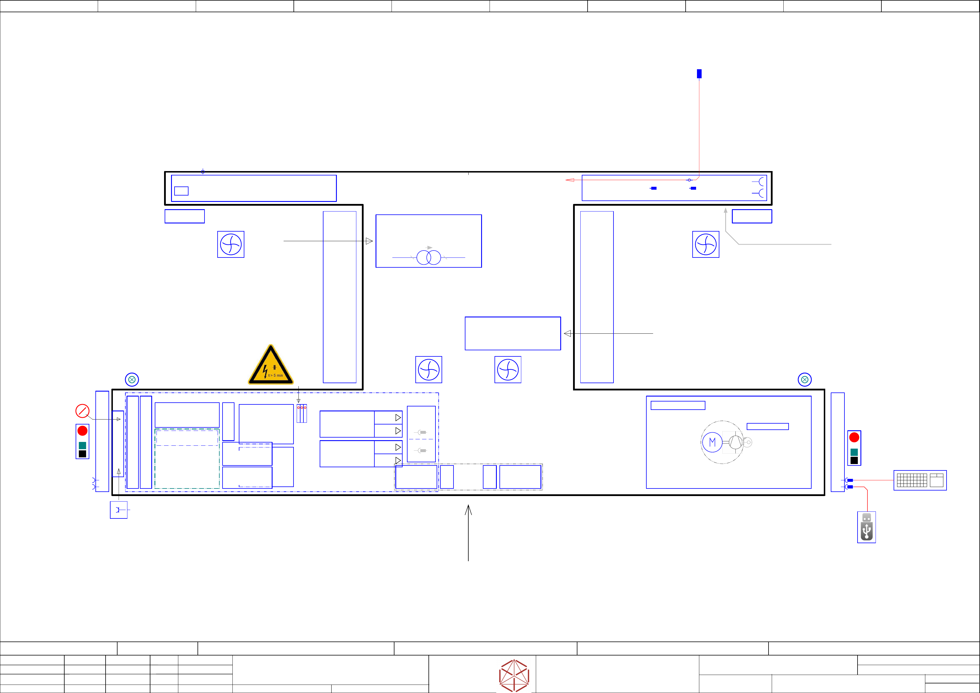
Function: Overview Graphics
==OVGR=TX/3
drawing number:
03110650-010201LE3
overview_graphics
o
v
erview_gr
aphics
o
v
erview_graphics
overview_graphics
GmbH & Co KG
ASM
Assembly Systems
Copyright reserved
Ed.
Original
Pingist
Date
Date
Modification
Appr
01.12.2016
Name
Version: Series from
V
ersion: S
eries f
r
om
V
ersion: Series from
Version: Series from
2016/Q4 TA500
2016/Q4 TA500
2016/Q4 TA500
2016/Q4 TA500
starting MC-Nr
.: TA500 2016/Q4 G. Pingist
Location 1
Location 1
Location 1
Location 1Location 2
Location 2
Location 2
Location 2
Main switch
Start
Emergency Stop
Stop
Start
Stop
Emergency Stop
Fan Flap 2
Fans
- Basic protection -
Fan Flap 1
PCB Transfer
Sercice_access
Sercice_access
Interface Extern Connections
Interface Extern Connections
Interface Extern Connections
Interface Extern Connections
-DIC
-FDC
Connector-
Field
3Ph/Mot4
3Ph/Mot3
3Ph/Mot2
3Ph/Mot1
USB keyboard with touch pad
(only for service)
==CH+CTRL/54.03
Service Testing-Point
DC 300 V IN/OUT
==PS005+ELS/38.03
ELS(electric_slide_in) SMPS & MGCU unit
ELS(electric_slide_in) SMPS & MGCU unit
ELS(electric_slide_in) SMPS & MGCU unit
ELS(electric_slide_in) SMPS & MGCU unit
- above -
==FLUID-M1.VAC
==FLUID-VAC_P
Vacuum_Pump
- Optional -
==FLUID/101.01
-U1
-U1
-U1
-U1
Pneumatic-group P001
Main_Pneumatics_connection
Main_valves
3Ph 400V
Transformer
Transformer
Tr
ansformer
Transformer
US voltage adaption kit (Option)
US voltage adaption kit (Option)
US voltage adaption kit (Option)
US voltage adaption kit (Option)
3P208V/400V/5,05A
==MPI/37.00
3Ph 200V
-PC
-PC
-PC
-PC
Control computer BoxPC-427D i3 2xPCIe
03114177
==CH+CTRL/54.02
4x SMEMA-Interface
==CO008+L1/87.07
LAN2 extern_Connection
RJ45
==CH+CTRL/54.05
-X1
-X1
-X1
-X1
Mains Connection
Mains Connection
Mains Connection
Mains Connection
CEE-connector
5-pole 6h 16A/400V
==MPI/37.03
Main-connection
Main-connection
Main-connection
Main-connection
air-pressure
air-pressure
air-pressure
air-pressure
p= 5 to 10bar
by 500NL/min
Service Socket
230VAC(110VAC)
10A
==MPI/37.04
1/N/PE
CAN Interface CIN
==CH+CTRL/54.00
-MGCU2
-MGCU2
-MGCU2
-MGCU2
Position controller MGCU
Gantry 2 axis X/Y
==CH+GA/57.00
-MGCU1
-MGCU1
-MGCU1
-MGCU1
Position controller MGCU
Gantry 1 axis X/Y
==CH+GA/55.00
Fuse- and Distribution PCB
==PS005+ELS/39.00
CAN- I/O control unit III
==DI/43.00
Main Power Input
==MPI/37.02
Monitor-2
Monitor-2
Monitor-2
Monitor-2
==CH+CTRL/54.05
USB A plug
USB-STICK 3.0(2.0)
Service (Data-handling)
==CH+CTRL/54.05
Control-elements-1
==CH+DI/49.00
Control-elements-2
==CH+DI/49.03
USB
Monitor-1
Monitor-1
Monitor-1
Monitor-1
==CH+CTRL/54.01
USB
Service
Fault indicator lamp 2
==CH+DI/52.05
Fault indicator lamp 1
==CH+DI/52.03
Hood switch S2
==CH+DI/50.04
Hood switch S1
==CH+DI/50.01
-CAP1
-CAP1
-CAP1
-CAP1
DC 300/150
Capacitor Bank
==PS005+ELS/38.00
==CSB+#
==CSB+#
==CSB+#
==CSB+#
Contactor Safety Bracker
+ELS/4 ==OV+PE/11.01 ==OV+PS005/13.04
-A2
Safety breaker
PCB Pre-/discharge assembly
==CSB/41.00
-PS3
-PS3
-PS3
-PS3
DC Out 27V/20A (COTi)
==PS005+ELS/39.02
-PS4
-PS4
-PS4
-PS4
DC Out 24V/20A (Control)
==PS005+ELS/39.03
-PS1
-PS1
-PS1
-PS1
Motion DC-Out1 300V
DC-Out2 160V
==PS005+ELS/38.00
-PS2
-PS2
-PS2
-PS2
DC-out 42V / 960W
==PS005+ELS/39.01
-TI1
-TI1
-TI1
-TI1
Trailing interface 1
==CH+GA/55.00
-TI2
-TI2
-TI2
-TI2
Tr
ailing interface 2
==CH+GA/57.00
-VBI1
-VBI1
-VBI1
-VBI1
Vision
Base-Interface 1
==CH+GA/56.05
-VBI2
-VBI2
-VBI2
-VBI2
Vision
Base-Interface 2
==CH+GA/58.05
-X2
-FCU
-FCU
-FCU
-FCU
X-FCU V2
X
-FCU V2
X-FCU V2
X-FCU V2
Location-1
Location-1
Location-1
Location-1
==COTi+Loc1/60.00
-FCU
-FCU
-FCU
-FCU
X-FCU V2
X
-FCU V2
X-FCU V2
X-FCU V2
Location-2
Location-2
Location-2
Location-2
==COTi+Loc2/63.00
2x Shuttle-Interface
==CH+PS/48.01
CAN3.EXT
access to Shuttle connection
Sheet
Size DIN A2
electric_schematic_TX
electric_schematic_TX
electric_schematic_TX
electric_schematic_TX
90012154-010301LE3
Replaced by
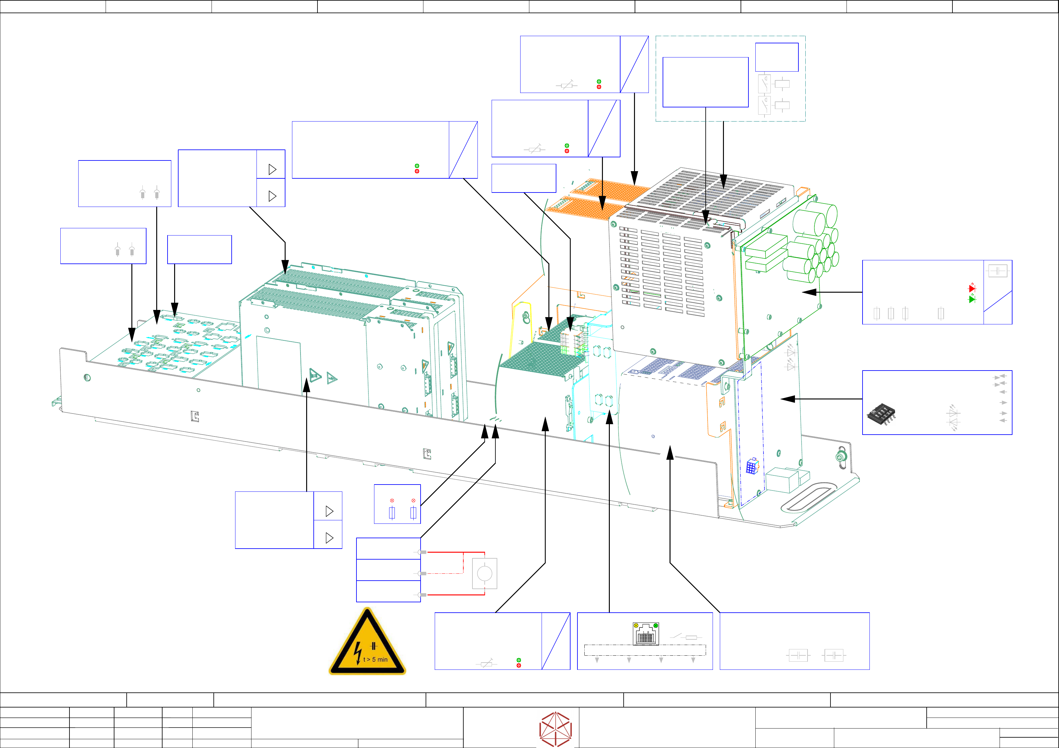
Overview_graphics
Overview_graphics
Overview_graphics
Overview_graphics
Power-Supplys, MGCU, Fuse & Distribution
Power-Supplys, MGCU, Fuse & Distribution
P
ower-Supplys, MGCU, Fuse & Distribution
Power-Supplys, MGCU, Fuse & Distribution
Replaced by
4
Weitergabe sowie Vervielfältigung dieser Unterlage, Verwertung und
Mitteilung des Inhalts nicht gestattet, soweit nicht ausdrücklich zugestanden.
Proprietary Data, company confidential.
All rights reserved
Copying of this document, giving it to others and the use or
communication of the contents thereof, are forbidden without express authority.
Doc. No.
Privileged business information.
Do not release
Offenders are liable to payment of damages. All rights are reserved in the
event of the grant or the registration of a utility model or design.
Zuwiederhandlungen verpflichten zu Schadenersatz. Alle Rechte vorbehalten,
insbesondere für den Fall der Patenterteilung oder GM-Eintragung vorbehalten.
Page:
Function: Overview Graphics
==OVGR=TX+ELS/4
drawing number:
03119265-010601LE3
overview_graphics
o
v
erview_gr
aphics
o
v
erview_graphics
overview_graphics
GmbH & Co KG
ASM
Assembly Systems
Copyright reserved
Ed.
Original
Pingist
Date
Date
Modification
Appr
01.12.2016
Name
Version: Series from
V
ersion: S
eries f
r
om
V
ersion: Series from
Version: Series from
2016/Q4 TA500
2016/Q4 TA500
2016/Q4 TA500
2016/Q4 TA500
starting MC-Nr
.: TA500 2016/Q4 G. Pingist
3Ph/Mot3
3Ph/Mot4
3~
3~
3~
3~
=
=
=
=
Overload
DC ok
Adjust
36-42V
-PS2
-PS2
-PS2
-PS2
AC/DC converter DC38V/23A 3P
AC/DC con
verter DC38V/23A 3P
AC/DC converter DC38V/23A 3P
AC/DC con
verter DC38V/23A 3P
PULS.QT40.361
03103331
DC Out 42V / Driver & Light_Cam.
DC Out 42V / Driver & Light_Cam.
DC Out 42V / Driver & Light_Cam.
DC Out 42V / Driver & Light_Cam.
==PS005/39.01
CAN1 CAN2 CAN3 CAN4
LAN
CAN-termination
(120 Ohm = off)
LAN to CAN_converter
DC 25V Puff1
DC 42V
DC 25V Puff2
discharge-
Head-buffer
RED: individual voltage
monitoring (on Board)
GREEN: Diagnostic OK
. . . . .
. . . . .
. . . . .
. . . . .
-F1
-F2
-F4
-F23
3Ph/Mot1
3Ph/Mot2
3~
3~
3~
3~
=
=
=
=
Vout1>220V
Vout1<220V
-PS1
-PS1
-PS1
-PS1
Converter AC3~ 380-415 V/DC300 and 160 V; 1,2kW
Converter AC3~ 380-415 V/DC300 and 160 V; 1,2kW
Conv
erter AC3~ 380-415 V/DC300 and 160 V; 1,2kW
Converter AC3~ 380-415 V/DC300 and 160 V; 1,2kW
PULS.QT40-999-70
03103087
Motion DC-Out1 300V / DC-Out2 160V
Motion DC-Out1 300V / DC-Out2 160V
Motion DC-Out1 300V / DC-Out2 160V
Motion DC
-Out1 300V / DC-Out2 160V
==PS005/38.00
3~
3~
3~
3~
=
=
=
=
3~
3~
3~
3~
=
=
=
=
Overload
DC ok
Adjust
24-28V
Overload
DC ok
Adjust
24-28V
Dip-Switch S1
CAN-Bus termination = on
Connector-field DI
Connector-field DI
Connector-field DI
Connector-field DI
-X21 to -X36
-X21 to -X36
-X21 to -X36
-X21 to -X36
<< I/O LED-Display
DC 300 V DC 160 V
-CAP1
-CAP1
-CAP1
-CAP1
Capacitor unit 38 mF including diagnostic master
Capacitor unit 38 mF including diagnostic master
Capacitor unit 38 mF including diagnostic master
Capaci
tor unit 38 mF including diagnostic master
PULS.PCS417.381
03103081
==PS005/38.00
-MGCU2
-MGCU2
-MGCU2
-MGCU2
Position controller MGCU-2
Gantry 2 axis X/Y
03117531
==CH+GA/57.00
-X303
DC300V_IN
DC300V_IN
DC300V_IN
DC300V_IN
==PS005/38.03
Service Testing point
Service Testing point
Service Testing point
Service Testing point
-X304
DC 300V_OUT
DC 300V_OUT
DC 300V_OUT
DC 300V_OUT
==PS005/38.03
-X305
GND
GND
GND
GND
==PS005/38.03
Extern Voltage measuring instrument,
with display, voltmeter
Sefaty-instructions
Sefaty-instructions
Sefaty-instructions
Sefaty-instructions
see Service-Dokument
see Service-Dokument
see Service-Dokument
see Service-Dokument
V
-CIN
-CIN
-CIN
-CIN
CAN Interface CIN
03108598
==CH+CTRL/54.00
-DI
-DI
-DI
-DI
CAN- I/O control unit III
CAN- I/O control unit III
CAN- I/O control unit III
CAN- I/O contr
ol unit III
03121427
==DI+/43.00
-FD.A1
-FD.A1
-FD.A1
-FD.A1
Fuse- and Distribution PCB TX
Fuse- and Distribution PCB TX
Fuse- and Distribution PCB TX
Fuse- and Distribution PCB TX
03114948
==PS005/39.00
-MGCU1
-MGCU1
-MGCU1
-MGCU1
Position controller MGCU-2
Gantry 1 axis X/Y
03117531
==CH+GA/55.00
-DIC
-DIC
-DIC
-DIC
Connector_field
Distributor TX
03123463-
==CH+DI/49.00
-PS3
-PS3
-PS3
-PS3
AC/DC converter DC24V/20A 3P
AC/DC converter DC24V/20A 3P
AC/DC converter DC24V/20A 3P
AC/DC con
verter DC24V/20A 3P
PULS.QT20.241
03055232
DC Out 28V COTi
DC Out 28V COTi
DC Out 28V COTi
DC Out 28V COTi
==PS005/39.02
-PS4
-PS4
-PS4
-PS4
AC/DC converter DC24V/20A 3P
AC/DC converter DC24V/20A 3P
AC/DC converter DC24V/20A 3P
AC/DC con
verter DC24V/20A 3P
PULS.QT20.241
03055232
==PS005/39.03
-A2
-A2
-A2
-A2
Safet
y breaker unit
PCB Pre-/discharge assembly
03104070
==CSB+/41.00
Control Safety_breaker_unit
03112066
-K5
-K5
-K5
-K5
Safety relay 2-chanel
SIE.3SK1121-2CB1
03114826-
-X300
3x AC 400V + PE
3x AC 400V + PE
3x AC 400V + PE
3x AC 400V + PE
Distribution Supplys
==PS005/38.06
-X102.ELS
primary-feed
3x400V AC / PE
==PS005/38.09
-F30
24V Shuttle
T 2,5A
-F31
42V Shuttle
T 6,3A
-FDC
-FDC
-FDC
-FDC
Connector_field
Fuse & Distribution
03122907-
24x OUT(24V)
40x IN(24V)
2x RS485
CAN1
CAN2
CAN3(Service)