Detailed Circuit Diagrams Folder.pdf - 第147页
Sheet Size DIN A2 electric_schematic_TX electric_schematic_TX electric_schematic_TX electric_schematic_TX 90012154-010301LE3 Replaced by Safety -Loop overview Safety -Loop overview Safety -Loop overview Safety -Loop over…
Sheet
Size DIN A2
electric_schematic_TX
electric_schematic_TX
electric_schematic_TX
electric_schematic_TX
90012154-010301LE3
Replaced by
Barcode reader Lane 2
Barcode reader Lane 2
Barcode reader Lane 2
Barcode reader Lane 2
Replaced by
140
Weitergabe sowie Vervielfältigung dieser Unterlage, Verwertung und
Mitteilung des Inhalts nicht gestattet, soweit nicht ausdrücklich zugestanden.
Proprietary Data, company confidential.
All rights reserved
Copying of this document, giving it to others and the use or
communication of the contents thereof, are forbidden without express authority.
Doc. No.
0 1 2 3 4 5 6 7 8 9
Privileged business information.
Do not release
Offenders are liable to payment of damages. All rights are reserved in the
event of the grant or the registration of a utility model or design.
Zuwiederhandlungen verpflichten zu Schadenersatz. Alle Rechte vorbehalten,
insbesondere für den Fall der Patenterteilung oder GM-Eintragung vorbehalten.
Page:
Function: Conveyor
==CO=SC01+COD/140
drawing number:
03135848-010101LX3
Shuttle_TX
Shut
tle_TX
Shut
tle_TX
Shut
tle_TX
GmbH & Co KG
A
SM
Assembly S
ystems
Copyright reserved
Ed.
Original
Pingist
Date
Date
Modification
Appr
01.12.2016
Name
Version: Series from
V
ersion: S
eries f
r
om
V
ersion: Series from
Version: Series from
2016/Q4 TA500
2016/Q4 TA500
2016/Q4 TA500
2016/Q4 TA500
starting MC-Nr
.: TA500 2016/Q4 G. Pingist
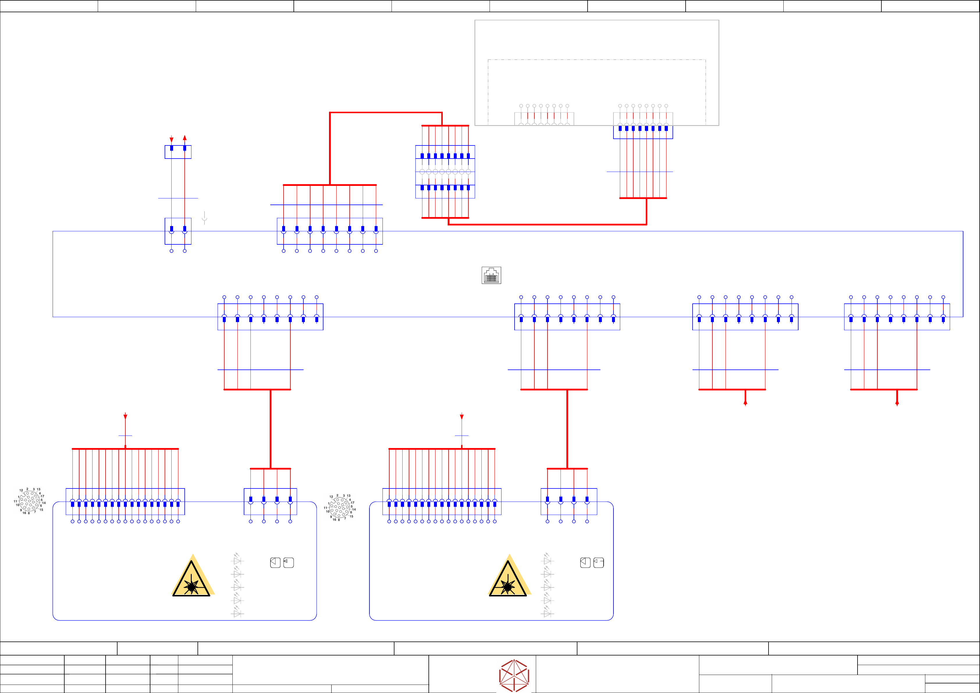
Schematic diagram
Pin assignment M12, 17-pin
Socket side view
Schematic diagram
Pin assignment M12, 17-pin
Socket side view
RD-
TD+
RD+
TD-
teach
RD-
TD+
RD+
TD-
teach
-P5
/139.6
-P4
/139.2
DB+
DC-
DB-
DA+
DD+
DA-
DC+
DC-
DC+
DA-
DD-
DD+
DA+
DB-
DB+
RD-
TD+
TD-
RD+
RD-
TD+
TD-
RD+
RD-
TD+
TD-
RD+
RD-
TD+
TD-
RD+
DD-
DC-
DC+
DA-
DD-
DA+
DB-
DB+
DD+
DC-
DC+
DA-
DD-
DA+
DB-
DB+
DD+
-DC5V
-DC5V
-DC5V
-DC5V
Power +5V
Power +5V
Power +5V
Power +5V
-[1]
-[1]
-[1]
-[1]
Lane RJ45
-SWITCH
-SWITCH
-SWITCH
-
SWITCH
Fast Ethernet 5-Port Switch
Fast Ethernet 5-Port Switch
F
ast Ethernet 5-Port Switch
Fast Ethernet 5-Port Switch
DGS-105 - 10/100/1000Mbit/s
03149956
03149956
03149956
03149956
==OV_SH+/128 ==OV_SH/131.3
-DC5V.JP
-DC5V.JP
-DC5V.JP
-DC5V.JP
-[5]
-[5]
-[5]
-[5]
-[5]
-[5]
-[5]
-[5]
Lane RJ45
-X2
-X2
-X2
-X2
1 2 3 4
-L2.TOP-X2
-L2.TOP-X2
-L2.TOP-X2
-L2.TOP-X2
M12 4pol.
1 2 3 4
-X1
-X1
-X1
-X1
1 2 3 4 5 6 7 8 9 10 11 12 13 14 15
GND
TD+
DC10..30V
CAN L
CAN H
TD-
TxD(AUX)
RxD(AUX
SensGND
Sensor 1
RD+(Host)
RD-
Result 1
Result 2
16 17
Result 1
Result 2
Sensor 2
TD+
RD+
TD-
RD-
LED
Data
Ready
Result
LNK TX
-L2.TOP
-L2.TOP
-L2.TOP
-L2.TOP
Bar
code-Scanner
Barcode-Scanner
Barcode-Scanner
Barcode-Scanner
LECTOR-620S-T11503
LECT
OR-620S-T11503
LECTOR
-620S-T11503
LECTOR-620S-T11503
Lane_2_Top
Lane_2_T
op
Lane_2_Top
Lane_2_Top
03101359-
==OV_SH/131.5
Laser-class 1
Laser
-class 1
Laser
-class 1
Laser-class 1
-X2
-X2
-X2
-X2
1 2 3 4
-L2.BOTTOM-X2
-L2.BOTTOM-X2
-L2.BOTTOM-X2
-L2.BOTTOM-X2
M12 4pol.
1 2 3 4
-X1
-X1
-X1
-X1
1 2 3 4 5 6 7 8 9 10 11 12 13 14 15
GND
TD+
DC10..30V
CAN L
CAN H
TD-
TxD(AUX)
RxD(AUX
SensGND
Sensor 1
RD+(Host)
RD-
Result 1
Result 2
16 17
Result 1
Result 2
Sensor 2
TD+
RD+
TD-
RD-
LED
Data
Ready
Result
LNK TX
-L2.BOTTOM
-L2.BOTTOM
-L2.B
OTTOM
-L2.BOTTOM
Barcode-Scanner
Barcode-Scanner
Barcode-Scanner
Barcode-Scanner
LECTOR-620S-T11503
LECT
OR-620S-T11503
LECTOR
-620S-T11503
LECTOR-620S-T11503
Lane_2_Bottom
Lane_2_B
ottom
Lane_2_Bottom
Lane_2_B
ottom
03101359-
==OV_SH/131.6
Laser-class 1
Laser
-class 1
Laser-class 1
Laser-class 1
-L2.TOP-X1
-L2.TOP-X1
-L2.TOP-X1
-L2.TOP-X1
1 2 3 4 5 6 7 8 9 10 11 12 13 14 15 16 17
-L2.BOTTOM-X1
-L2.BOTTOM-X1
-L2.BOTTOM-X1
-L2.BOTTOM-X1
1 2 3 4 5 6 7 8 9 10 11 12 13 14 15 16 17
2000 mm
03111957
03111957
03111957
03111957
-01
-01
-01
-01
-W42
-W42
-W42
-W42
2000 mm
03111957
03111957
03111957
03111957
-01
-01
-01
-01
-W43
-W43
-W43
-W43
-X3P1
-X3P1
-X3P1
-X3P1
RJ45
1 2 3 4 5 6 7 8
-[1]
-[1]
-[1]
-[1]
3000 mm
8x0,14
Patchkabel Cat. 6a FTP
03148161
03148161
03148161
03148161 -01
-01
-01
-01
WH-OG
OG
WH-GN
BU
WH-BU
GN
WH-BN
BN
1
2 3 4 5 6 87
BI_DC+
BI_DB+
BI_DD+
BI_DD-
BI_DA+
BI_DA-
BI_DC-
BI_DB-
LAN4
-X4P1
-X4P1
-X4P1
-X4P1
RJ45
3D Coplanarity
3D Coplanarity
3D Coplanarity
3D Coplanarity
1 2 3 4 5 6 87
BI_DC+
BI_DB+
BI_DD+
BI_DD-
BI_DA+
BI_DA-
BI_DC-
BI_DB-
-PC.LAN
-PC.LAN
-PC.LAN
-PC.LAN
LAN-Car
d 2x PCI-Express Gigabit
L
AN-Card 2x PCI-Express Gigabi
t
LAN-Card 2x PCI-Express Gigabit
LAN-Card 2x PCI-Express Gigabit
03118416
LAN3
-X3P1
-X3P1
-X3P1
-X3P1
RJ45
-PC
-PC
-PC
-PC
Control computer
Control computer
Control computer
Control computer
Bo
xPC-427D i3 2xPCIe
B
oxPC-427D i3 2xPCIe
B
oxPC-427D i3 2xPCIe
BoxPC-427D i3 2xPCIe
100 mm
2x0,25
part from Hub
03104923
03104923
03104923
03104923 -01
-01
-01
-01
-W90
-
W90
-W90
-W90
-DC5V
-DC5V
-DC5V
-DC5V
1 2
+ -
+
DC 5V
-
GND
Pin_assignment
Pin1(+)
Pin2(-)
8
L1_DD-
1
L1_DA+
2
L1_DA-
3
L1_DB+
4
L1_DC+
5
L1_DC-
7
L1_DD+
6
L1_DB-
87654321
L4_DA+
1 2
L4_DA-
L4_DD-
8
L4_DD+
7
L4_DB-
6
L4_DC-
5
L4_DC+
4
L4_DB+
3
87654
2000 mm
4x0,25
SSL-23J04-G02ME
03104896
03104896
03104896
03104896 -01
-01
-01
-01
-W98
-
W98
-W98
-W98
Cable w/ connector 2m SSL
-2J04-G02ME
1 2 3
-[4]
-[4]
-[4]
-[4]
Lane RJ45
L4_DA+
1 2
L4_DA-
L4_DD-
8
L4_DD+
7
L4_DB-
6
L4_DC-
5
L4_DC+
4
L4_DB+
3
-[4]
-[4]
-[4]
-[4]
876541 2 3
2000 mm
4x0,25
SSL-23J04-G02ME
03104896
03104896
03104896
03104896 -01
-01
-01
-01
-W97
-
W97
-W97
-W97
Cable w/ connector 2m SSL
-2J04-G02ME
-[3]
-[3]
-[3]
-[3]
Lane RJ45
L4_DA+
1 2
L4_DA-
L4_DD-
8
L4_DD+
7
L4_DB-
6
L4_DC-
5
L4_DC+
4
L4_DB+
3
-[2]
-[2]
-[2]
-[2]
Lane RJ45
L4_DA+
1 2
L4_DA-
L4_DD-
8
L4_DD+
7
L4_DB-
6
L4_DC-
5
L4_DC+
4
L4_DB+
3
876541 2 3
-[3]
-[3]
-[3]
-[3]
876541 2 3
-[2]
-[2]
-[2]
-[2]
2000 mm
4x0,25
SSL-23J04-G02ME
03104896
03104896
03104896
03104896 -01
-01
-01
-01
-W96
-
W96
-W96
-W96
Cable w/ connector 2m SSL
-2J04-G02ME
2000 mm
4x0,25
SSL-23J04-G02ME
03104896
03104896
03104896
03104896 -01
-01
-01
-01
-W95
-
W95
-W95
-W95
Cable w/ connector 2m SSL
-2J04-G02ME
3000 mm
8x0,14
Patchkabel Cat. 6a FTP
03152764
03152764
03152764
03152764 -01
-01
-01
-01
-W99
-W99
-W99
-W99
1 2 3 4 5 6 87
LAN adapter
RJ45
1234568 7
LAN adapter
RJ45
-X2
-X2
-X2
-X2
RJ45
1 2 3 4 5 6 7 8
-X1
-X1
-X1
-X1
RJ45
12345678
-X3
/139.7
-X4
/139.8
-LAN5V
/139.3
-LANGND
/139.3
Contacts of
SACC-FS-17PCON SCO
Contacts of
SACC-FS-17PCON SCO
Sheet
Size DIN A2
electric_schematic_TX
electric_schematic_TX
electric_schematic_TX
electric_schematic_TX
90012154-010301LE3
Replaced by
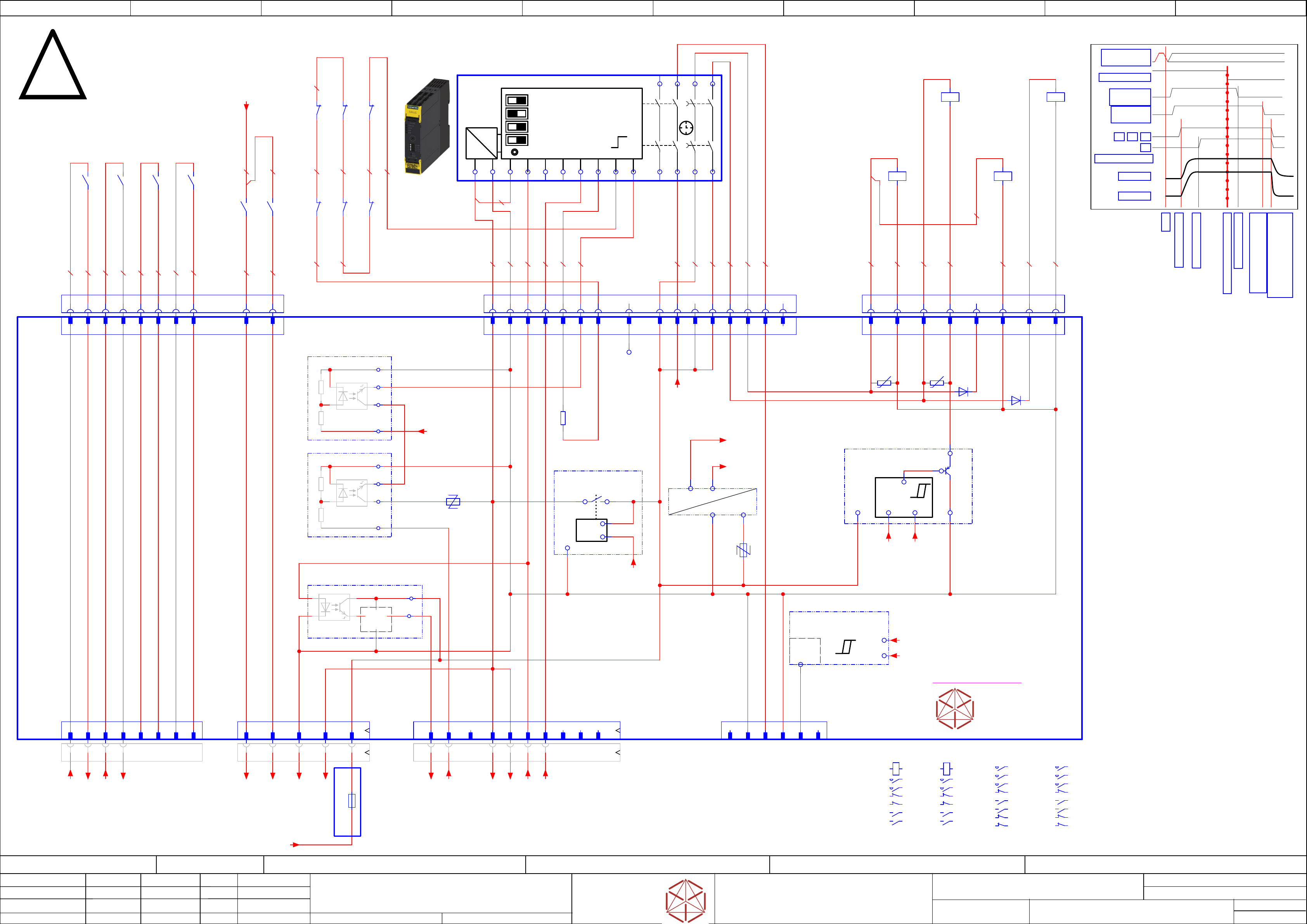
Safety-Loop overview
Safety-Loop overview
Safety-Loop overview
Safety-Loop overview
contactor based safety breaker: logic
contactor based safety breaker: logic
contactor based saf
ety breaker: logic
contactor based safety breaker: logic
Replaced by
141
Weitergabe sowie Vervielfältigung dieser Unterlage, Verwertung und
Mitteilung des Inhalts nicht gestattet, soweit nicht ausdrücklich zugestanden.
Proprietary Data, company confidential.
All rights reserved
Copying of this document, giving it to others and the use or
communication of the contents thereof, are forbidden without express authority.
Doc. No.
0 1 2 3 4 5 6 7 8 9
Privileged business information.
Do not release
Offenders are liable to payment of damages. All rights are reserved in the
event of the grant or the registration of a utility model or design.
Zuwiederhandlungen verpflichten zu Schadenersatz. Alle Rechte vorbehalten,
insbesondere für den Fall der Patenterteilung oder GM-Eintragung vorbehalten.
Page:
Function: Emergency Loop Documentation
==EMG=TX_EMG+CSB/141
drawing number:
03112066-010501LE3
Emergency Loop Documentation
Emer
gency Loop Documentation
Emer
gency Loop Documentation
Emer
gency Loop Documentation
GmbH & Co KG
A
SM
Assembly S
ystems
Copyright reserved
Ed.
Original
Pingist
Date
Date
Modification
Appr
01.12.2016
Name
Version: Series from
V
ersion: S
eries f
r
om
V
ersion: Series from
Version: Series from
2016/Q4 TA500
2016/Q4 TA500
2016/Q4 TA500
2016/Q4 TA500
starting MC-Nr
.: TA500 2016/Q4 G. Pingist
LOGIC
=~
=
+ -
+ -
+ -
+ -
1 | Autostart/Monitored Start
1 | Autostart/Monitored Start
1 | Autostart/Moni
tored Start
1 | Autostart/Monitored Start
2 | Cross Fault Detection Off/On
2 | Cr
oss F
aul
t Detection Of
f/On
2 | Cr
oss Fault Detection Off/On
2 | Cross Fault Detection Off/On
3 | 2 single ch. sensors / 1 double channel Sensor
3 | 2 single ch. sensors / 1 double channel Sensor
3 | 2 single ch. sensors / 1 double channel Sensor
3 | 2 single ch. sensors / 1 double channel Sensor
4 | Startup Test Yes/No
4 | Startup Test Yes/No
4 | Startup Test Yes/No
4 | Startup T
est Yes/No
SET / RESET
SET / RESET
SET / RESET
SET / RESET
T
T
T
T
- not used -
Parts shown at this page
are for safety related purposes.
To be replaced by
original parts only!
03108631-010301le3
Timing chart
S
S
S
S
Start
Start
Start
Start
Precharge done
Precharge done
Precharge done
Precharge done
Emergency STOP event
Emergency STOP event
Emergency STOP event
Emergency STOP event
K1,K2, K3, K4 off delay;
K1,K2, K3, K4 off delay;
K1,K2, K3, K4 off delay;
K1,K2, K3, K4 off delay;
Discharge external Cap
Discharge external Cap
Discharge external Cap
Discharge external Cap
-->Power of
f
-->Power off
-->Power off
-->Power off
Safety relais off
Safety relais off
Safety relais off
Safety relais off
Safety relaais off delay
Safety relaais off delay
Safety relaais off delay
Safety relaais off delay
> 100 ms; <180 ms
> 100 ms; <180 ms
> 100 ms; <180 ms
> 100 ms; <180 ms
Precharge start
Precharge start
Precharge start
Precharge start
DC 300 V
DC 300 V
DC 300 V
DC 300 V
DC 160 V
DC 160 V
DC 160 V
DC 160 V
K2
K2
K2
K2
POWER_ENABLE
POWER_ENABLE
POWER_ENABLE
POWER_ENABLE
K1
K1
K1
K1 K4
K4
K4
K4K3
K3
K3
K3
PCC output
PCC output
PCC output
PCC output
delayed
delayed
delayed
dela
yed
PCC output
PCC output
PCC output
PCC output
not delayed
not dela
y
ed
not dela
y
ed
not dela
yed
EMG_Loop_OK
EMG_Loop_OK
EMG_Loop_OK
EMG_Loop_OK
SW_CTRL_ON
SW_CTRL_ON
SW_CTRL_ON
SW_CTRL_ON
Start
Start
Start
Start
Safety_Loop 1&2
Safety_Loop 1&2
Safety_Loop 1&2
Saf
ety_Loop 1&2
to Distributor -X22
to Distributor -
X22
to Distributor -X22
to Distributor -X22
4x Safet
y Loop Extern
4x Saf
et
y Loop Extern
4x Saf
et
y Loop Extern
4x Saf
ety Loop Extern
ITS4141
Load-switch
&
-F1
-F2
24V_PCC
24V_PCC
24V_PCC
24V_PCC
&
GND_Safety
GND_Safety
GND_Safety
GND_Saf
ety
ITS4141
Load-switch
&
seperated circuit diagram
A1
INK
IN1
IN2
A2
13
23
37
47
INF
INS
38
48
T2
T1
PAR
-K5
-K5
-K5
-K5
Safety relay 2-chanel
Saf
et
y r
ela
y 2-chanel
Saf
ety relay 2-chanel
Safety relay 2-chanel
Safety relay 2NO S=0, 2NO, S=1 (50 ms - 3000ms)
Saf
ety relay 2NO S=0, 2NO, S=1 (50 ms - 3000ms)
Safety relay 2NO S=0, 2NO, S=1 (50 ms - 3000ms)
Safety relay 2NO S=0, 2NO, S=1 (50 ms - 3000ms)
SIE.3SK1121-2CB41
03114826
14
24
Safety Relais connect
-X100.CSB
-X100.CSB
-X100.CSB
-X100.CSB
-K1
-K1
-K1
-K1
Relay Safety
300V, 160V
A1
A2
A1 A2
1 2
3 4
2221
.2
3132
.2
1413
4443
.1
SIE.3TC4417-0AB4
-K3
-K3
-K3
-K3
Relay Safety
42V, 24V
A1
A2
1 2
3 4
5 6
2221
5453
.0
6463
.0
7271
8281
.2
EAT.DILM17-01(RDC24)
-K4
-K4
-K4
-K4
Relay
Pre-charge
300V, 160V
A1
A2
1 2
3 4
5 6
2122
.2
5453
.1
6463
.1
7271
8281
EAT.DILM17-01(RDC24)
OUT2_ND
DC 24V Safety controlled PL=d
3
GND Safety
8
Loop-CLSD
A5
Loop2-IN
B1
nc
B2
Loop1_IN
A3
Loop ext 1-1
1
Loop ext 1-2
2
Loop ext 2-1
3
Loop ext 2-2
4
Loop ext 3-1
5
Loop ext 3-2
6
Loop ext 4-1
7
Loop ext 4-2
8
A5 B18
GND Safety
2
GND Safety
4
1
1
2
2
3
3
4
4
5
5
6
6
7
7
8
8
9
9
10
10
CH2-OK
16
16
CH1-OK
15
15 5
24V-PCC
B5
24V-PCC
B6
B5
nc
1
PPWR-present
5
nc
6
-A2
-A2
-A2
-A2
Safet
y breaker
Safety breaker
Saf
ety breaker
Safety breaker
PCB Pre-/discharge assembly
PCB Pr
e-/discharge assembly
PCB Pre-/discharge assembly
PCB Pr
e-/discharge assembly
-X28.CSB
-X28.CSB
-X28.CSB
-X28.CSB
AuxContacts
-X28
-X28
-X28
-X28
AuxContacts in
-X27.CSB
-X27.CSB
-X27.CSB
-
X27.CSB
Safety
contactor
-X30
-X30
-X30
-X30
Safet
y
Loop extern
-X24B
-X24B
-X24B
-X24B
Safety
control signals
-X24B.CSB
-X24B.CSB
-X24B.CSB
-X24B.CSB
Safety control
signals to FDB
-W10
-X29.CSB
-X29.CSB
-X29.CSB
-X29.CSB
Safety Loop
& Signals
extern
-W11.1
-X29
-X29
-X29
-X29
Safet
y Loop
& Signals
-X31
-X31
-X31
-X31
Auxi
liary
(RFU signals)
-K2
-K2
-K2
-K2
Relay Safety
300V, 160V;
Power enable
A1
A2
A1 A2
1 2
3 4
2221
.2
3231
.2
1413
4344
.2
SIE.3TC4417-0AB4
START_SIG
Safety Start
Signal input
A6
A6
0,75 YE0,75 YE
-K3
-K3
-K3
-K3
81
82
-K4
-K4
-K4
-K4
22
21
-K1
-K1
-K1
-K1
21
22
-K1
-K1
-K1
-K1
32
31
-K2
-K2
-K2
-K2
21
22
-K2
-K2
-K2
-K2
31
32
0,75 YE
0,75 YE 0,75 YE
0,75 YE
0,75 YE
24V0
Safety unit
5
24V_PCC
7
7
nc
A4
nc
B3
nc
B4
B2 B3 B4A4 B6 A3
0,5 PK
0,5 WH
0,5 PK
0,5 PK
0,5 WH
0,5 WH
0,5 PK
0,5 YE
-K3
-K3
-K3
-K3
63
64
-K3
-K3
-K3
-K3
53
54
-K4
-K4
-K4
-K4
53
54
-K1
-K1
-K1
-K1
43
44
0,5 YE
0,5 YE
-K4
-K4
-K4
-K4
63
64
0,5 YE
0,5 YE
0,5 YE
0,5 YE
0,5 BN
0,5 BN
0,5 YE
0,5 YE
0,5 YE
0,5 YE
-K2
-K2
-K2
-K2
44
43
0,5 BN
0,5 WH
0,5 YE
0,5 YE
0,5 YE
0,5 BN
0,5 PK
0,5 PK
0,5 PK
0,5 YE
0,5 BN
0,5 BN
0,5
BN
-X30.CSB
-X30.CSB
-X30.CSB
-X30.CSB
Safet
y
Loop Extern
-W11.2
1 2 3 4 5 6 7 8
-F11
-F11
-F11
-F11
Supp1_SSK_RDY
6,3A
6,3A
6,3A
6,3A
A2 Fuse & Distripution
1 2 3 4 5 6 7 8
nc
9 10 11
nc
12 13 14 15 16
nc
15
OUT2_ND
13
OUT2_D
16
nc
1
K1-A1
1 2
2
GND
8
8
GND
14
OUT1_D
6
6
GND
5
5
A3-K1
7
7
K4-A1
-X100
-X100
-X100
-X100
Safet
y relais connect
-X27
-X27
-X27
-X27
Safet
y
contactor
3 4
3
K2-A1
4
GND/K5
-R42
60VAC(100mW)
-R43
60VAC(100mW)
-D18
1
24V_PCC
2
GND
3
Loop1_IN
4
Loop2_IN
5
T2
6
START
7
TestLoopIn
8
nc
-R128
0R
Test_loop_IN
+
+
-
-K1
-K1
-K1
-K1
Safety loop
closed signal
24V0
L_CLSD
9
24V0
10
24Vext
11
24V0
12
24V0
-D50
-P300.pbc
-P300.pbc
-P300.pbc
-P300.pbc
Voltage-Trigger
300V precharge bypass control
Out
GND
24V0
24V.Safe
24V.Safe
24V.Safe
24V
.Safe
Safe DC
internal supply
24VSafe
24V0
-K2
-K2
-K2
-K2 Start_loop
-
+
+
in
out
GND
DIAGN_K_N
-K3
-K3
-K3
-K3 Start_loop
-
+
+
in
out
GND
START_SIG
24V_PCC
24V_PCC
24V_PCC
24V_PCC
PCC supply
undervoltage lockout
OUT
24V_PCC
IN
24V0
DIAG
U_Mon
-Out
-PPWR.PRESENT
-PPWR.PRESENT
-PPWR.PRESENT
-PPWR.PRESENT
Voltage-Trigger
300V/160V PPWR-present
(300V > 60V & 160V > 60V)
P300V
P160V
-DI0_Safety_Loop_OK
+DI/142.1
-Loop2-End
-Loop2-End
-Loop2-End
-Loop2-End
+DI/142.1
-Loop1_Begin
-Loop1_Begin
-Loop1_Begin
-Loop1_Begin
+DI/142.1
-Safety_Start_SSK
+DI/142.1
-Loop2_Begin
-Loop2_Begin
-Loop2_Begin
-Loop2_Begin
+DI/142.1
-Loop1-End
-Loop1-End
-Loop1-End
-Loop1-End
+DI/142.1
==+-24V_F12_Aux
-Safety_Loop1_ext.in
+DI/142.2
-Safety_Loop1_ext.out
+DI/142.2
-Safety_Loop2_ext.in
+DI/142.2
-Safety_Loop2_ext.out
+DI/142.2
-GND_1
-CH1-OK
-CH2-OK
-PCC-POWER-OK
DC 24 V
from Power Supply PS4
24V-Supply
-P300V
-P160V
VDIFFMON1
300V
VDIFFMON2
160V
24VSafe
Safe supply
P_GND
Power Ground
DIAGN_K_N
==CSB=TX+/42.5
DIAGN_RD_N
Sheet
Size DIN A2
electric_schematic_TX
electric_schematic_TX
electric_schematic_TX
electric_schematic_TX
90012154-010301LE3
Replaced by
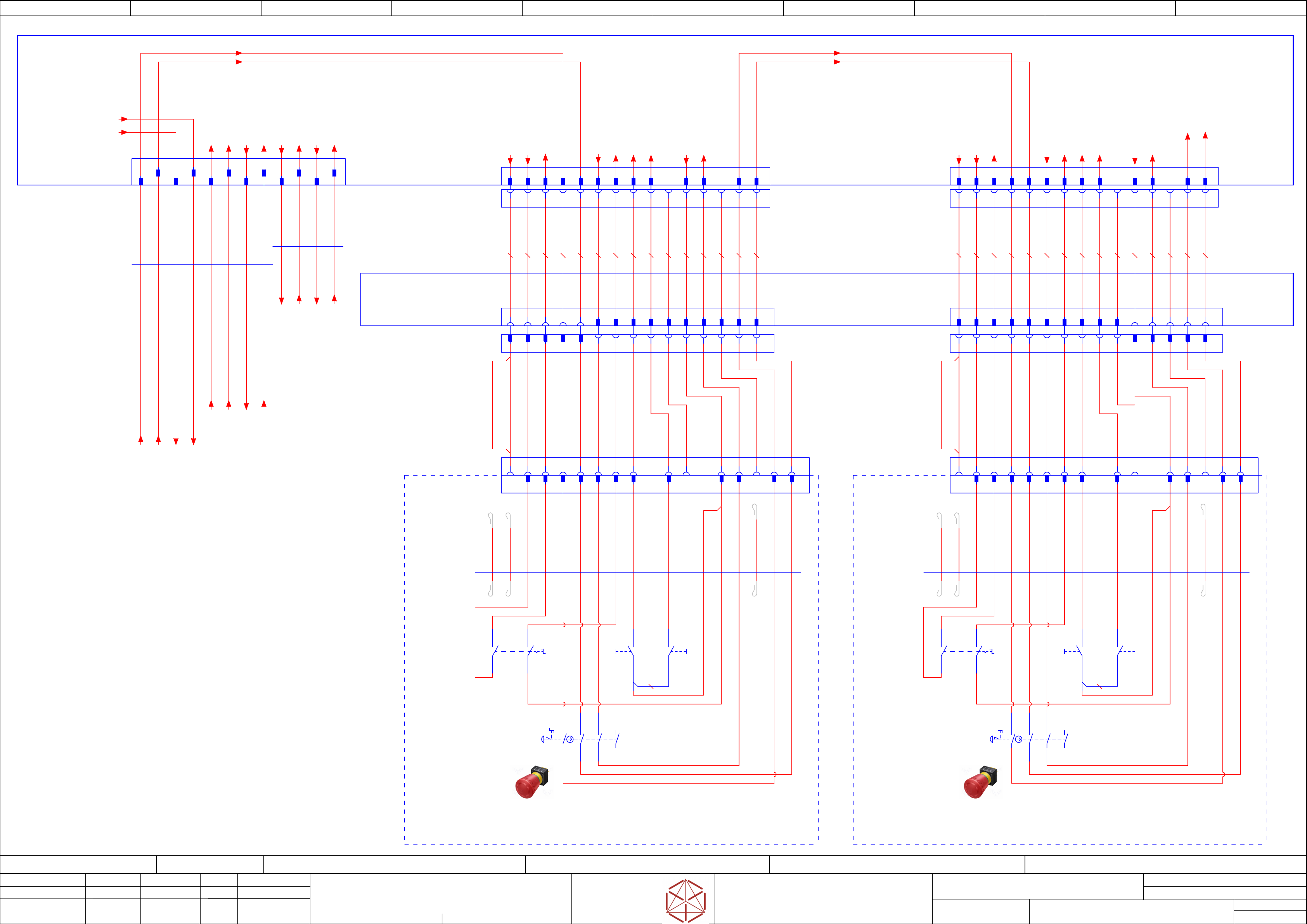
Safety-Loop overview
Safety-Loop overview
Safety-Loop overview
Safety-Loop overview
Emergency-Stop Start/Stop-Buton
Emergency-Stop Start/Stop-Buton
Emer
gency-Stop Start/Stop-Buton
Emergency-Stop Start/Stop-Buton
Replaced by
142
Weitergabe sowie Vervielfältigung dieser Unterlage, Verwertung und
Mitteilung des Inhalts nicht gestattet, soweit nicht ausdrücklich zugestanden.
Proprietary Data, company confidential.
All rights reserved
Copying of this document, giving it to others and the use or
communication of the contents thereof, are forbidden without express authority.
Doc. No.
00 01 02 03 04 05 06 07 08 09
Privileged business information.
Do not release
Offenders are liable to payment of damages. All rights are reserved in the
event of the grant or the registration of a utility model or design.
Zuwiederhandlungen verpflichten zu Schadenersatz. Alle Rechte vorbehalten,
insbesondere für den Fall der Patenterteilung oder GM-Eintragung vorbehalten.
Page:
Function: Emergency Loop Documentation
==EMG=TX_EMG+DI/142
drawing number:
Emergency Loop Documentation
Emer
gency Loop Documentation
Emer
gency Loop Documentation
Emer
gency Loop Documentation
GmbH & Co KG
A
SM
Assembly S
ystems
Copyright reserved
Ed.
Original
Pingist
Date
Date
Modification
Appr
01.12.2016
Name
Version: Series from
V
ersion: S
eries f
r
om
V
ersion: Series from
Version: Series from
2016/Q4 TA500
2016/Q4 TA500
2016/Q4 TA500
2016/Q4 TA500
starting MC-Nr
.: TA500 2016/Q4 G. Pingist
1 2 3 4 5 6 7 8 9 10 11 12 13 14 15
-X24.DIC
-X24.DIC
-X24.DIC
-
X24.DIC
1 2 3 4 5 6 7 8 9 10 11 12 13 14 15
-X1.CE2
-X1.CE2
-X1.CE2
-X1.CE2
1 2 3 4 5 6 7 8 9 10 11 12 13 14 15 1 2 3 4 5 6 7 8 9 10 11 12 13 14 15
Safety_Loop
Safety_Loop
Safety_Loop
Saf
ety_Loop
to Connector
to Connector
to Connector
to Connector
X25
X25
X25
X25
Safety-Loop
Saf
ety-Loop
Safet
y-Loop
Safety-Loop
from Connector -X36
from Connector -X36
fr
om Connector -X36
from Connector -X36
Safety_Loop 1&2
Safety_Loop 1&2
Safety_Loop 1&2
Safety_Loop 1&2
to Conntactor_Safety_Breaker CSB
to Conntactor_Saf
ety_Break
er CSB
to Conntactor_Safety_Breaker CSB
to Conntactor_Safety_Breaker CSB
X29
X29
X29
X29
Safety_Loop extern
Saf
ety_Loop extern
Safety_Loop extern
Saf
ety_Loop extern
Optional Machine
Optional Machine
Optional Machine
Optional Machine
seperated circuit diagram
2 3 4 5 6 7 8 10 11 12 13 14 15
12 3 4 5 6 7 8 10 11 12 13 14 151
1
2 3 4 5 7 86 11 13
-DI
-DI
-DI
-DI
<Empty identifier>
Distributor TX
Distributor TX
Distributor TX
Distributor TX
03121315
10 15
4660 mm
16x0,34
UNITRONIC® LiYY A
03112131
03112131
03112131
03112131
-W41
-W41
-W41
-W41
11 13
10 15 1 2 3 4 5 7 86
1 2 3 4 5 6 7 89 12 14
9 12 14
WH
BN
GN
YE
GY
PK
BU
RD
BK
VT
GYPK
RDBU
WHGN
BNGN
WHYE
YEBN
3630 mm
16x0,34
UNITRONIC® LiYY A
03112231
03112231
03112231
03112231
-W42
-W42
-W42
-W42
WH
BN
GN
YE
GY
PK
BU
RD
BK
VT
GYPK
RDBU
WHGN
BNGN
WHYE
YEBN
11
1310 159 12 14
6 7 8 109
Control elements 2
Control elements 2
Control elements 2
Control elements 2
(GCU side)
(GCU side)
(GCU side)
(GCU side)
Start / Stop 2
Start / Stop 2
Start / Stop 2
Start / Stop 2
==DI-DI
-X24
==DI-DI-X24
==DI-DI-X24
==DI-DI-X24
Mini MATE-N-LOK Socket 15-pin
TYCO.172163-1
1 2 3 4 5 6 7 8 10 13
Control elements 1
Control elements 1
Control elements 1
Control elements 1
(Power supply side)
(P
ower supply side)
(Power supply side)
(Power supply side)
Start / Stop 1
Start / Stop 1
Start / Stop 1
Start / Stop 1
==DI=TX_EMG-DI-
X23
==DI=TX_EMG-DI-X23
==DI=TX_EMG-DI-X23
==DI=TX_EMG-DI
-X23
Mini MATE-N-LOK Socket 15-pin
TYCO.172163-1
10 139 11 12 14 151 2 3 4 5 6 7 8 9 11 12 14 15
Control elements 2
Control elements 2
Control elements 2
Control elements 2
(GCU side)
(GCU side)
(GCU side)
(GCU side)
Start / Stop 2
Start / Stop 2
Start / Stop 2
Start / Stop 2
-X24
-
X24
-X24
-X24
Mini MATE-N-L
OK Socket 15-pin
TYCO.172163-1
1 2 3 4 5 6 7 8
Control elements 1
Control elements 1
Control elements 1
Control elements 1
(Power supply side)
(P
ower supply side)
(Power supply side)
(Power supply side)
Start / Stop 1
Start / Stop 1
Start / Stop 1
Start / Stop 1
-X23
-
X23
-X23
-X23
Mini MATE-N-L
OK Socket 15-pin
TYCO.172163-1
9 11 12 14 156 7 8 91310 10
-X23.DI
-X23.DI
-X23.DI
-X23.DI
TYCO
.172171-1
Mini MATE-N-LOK Plug 15-pin
10 1511 139 12 141 2 3 4 5 6 7 8
-X24.DI
-X24.DI
-X24.DI
-
X24.DI
TYCO.172171-1
Mini MATE-N-LOK Plug 15-pin
1 2 3 4 5 6 7 8 10 1511 139 12 14
1 2 3 54 11 13 1412 15
0,5 WH
0,5 YE
0,5 YE
0,5 YE
0,5 YE
0,5 YE
0,5 YE
0,5 BN
0,5 YE
0,5 BN
0,5 YE
0,5 YE
0,5 YE
0,5 YE
0,5 YE
0,5 WH
0,5 YE
0,5 YE
0,5 YE
0,5 YE
0,5 YE
0,5 YE
0,5 BN
0,5 YE
0,5 BN
0,5 YE
0,5 YE
0,5 YE
0,5 YE
0,5 YE
-DIC
-DIC
-DIC
-DIC
Distributor TX
Distributor TX
Distributor TX
Distributor TX
Connector field
1 2 3 4 5 11 12 13 14 15
Safety-Loop & Signals
Safety-Loop & Signals
Safet
y-Loop & Signals
Safety-Loop & Signals
from
from
from
f
rom
Power supply SMPS
Power supply SMPS
Power supply SMPS
Power supply SMPS
=TX_EMG+DI-DI
-X22
=TX_EMG+DI-DI-X22
=TX_EMG+DI-DI
-X22
=TX_EMG+DI-DI-X22
DYNAMIC D-2100D Tab 2x6-pin X key panel type
TYCO.1-1318114-6
A1
B1
A2
B2
A3 A4
B3 B4
A5 A6
B5 B6
570 mm
6x0,61
Single core UL/cUL Style
03112103
03112103
03112103
03112103 -02
-02
-02
-02
-W11.1
-
W11.1
-W11.1
-W11.1
620 mm
4x0,61
Single core UL/cUL Style
03112103
03112103
03112103
03112103
-02
-02
-02
-02
-W11.2
-W11.2
-W11.2
-W11.2
1 2 3 4 5 6 7 8 9 10 11 12 13 14 15
-X23.DIC
-X23.DIC
-X23.DIC
-X23.DIC
1 2 3 4 5 6 7 8 9 10 11 12 13 14 15
-X1.CE1
-X1.CE1
-X1.CE1
-X1.CE1
Location-1
Location-1
Location-1
Location-1
Control elements EmergencyStop/Start/Stop
Contr
ol elements EmergencyStop/Start/Stop
Control elements EmergencyStop/Start/Stop
Contr
ol elements EmergencyStop/Start/Stop
03110694
-U1
-U1
-U1
-U1
Location-2
Location-2
Location-2
Location-2
Control elements EmergencyStop/Start/Stop
Contr
ol elements EmergencyStop/Start/Stop
Control elements EmergencyStop/Start/Stop
Contr
ol elements EmergencyStop/Start/Stop
03110694
-U2
-U2
-U2
-U2
-U2-X1.CE
-U2-X1.CE
-U2-X1.CE
-U2-X1.CE
5
Safety_Loop2_IN
6
24V
4
Safety_Loop1_IN
12
Emergency_Stop
14
Safety_Loop1_OUT
15
Safety_Loop2_OUT
2
SW_Control_on
3
Start_Button
7
S_Start_Button
8
S_Stop_Button
11
24V
9
S_Button_COTi
21
22
-S2.1
-S2.1
-S2.1
-S2.1
2NC
EmergencyStop
Emer
gencyStop
EmergencyStop
EmergencyStop
11
12
21
22
-S2.2
-S2.2
-S2.2
-S2.2
2NC
11
12
500 mm
16x0,34
UNITRONIC® LiYY A
-U2-W1
-U2-W1
-U2-W1
-U2-W1
BN
GN
YE
GY
PK
BU
RD
BK
VT
GYPK
RDBU
-S1
-S1
-S1
-S1
2NO
Start
Start
Start
Start
13
14
23
24
-S3
-S3
-S3
-S3
1NO
Stop
Stop
Stop
Stop
3
4
BNGN
WHYE
WH
YEBN
-nc
-nc
-nc -nc
-S4
-S4
-S4
-S4
1NO
COTi
CO
Ti
COTi
COTi
3
4
WHGN
-nc
-nc
BK (J1) 0,34
400 mm
Bridge-J1
-U1-X1.CE
-U1-X1.CE
-U1-X1.CE
-U1-X1.CE
5
Safety_Loop2_IN
6
24V
4
Safety_Loop1_IN
12
Emergency_Stop
14
Safety_Loop1_OUT
15
Safety_Loop2_OUT
2
SW_Control_on
3
Start_Button
7
S_Start_Button
8
S_Stop_Button
11
24V
9
S_Button_COTi
21
22
-S2.1
-S2.1
-S2.1
-S2.1
2NC
EmergencyStop
Emer
gencyStop
EmergencyStop
EmergencyStop
11
12
21
22
-S2.2
-S2.2
-S2.2
-S2.2
2NC
11
12
500 mm
16x0,34
UNITRONIC® LiYY A
-U1-W1
-U1-W1
-U1-W1
-U1-W1
BN
GN
YE
GY
PK
BU
RD
BK
VT
GYPK
RDBU
-S1
-S1
-S1
-S1
2NO
Start
Start
Start
Start
13
14
23
24
-S3
-S3
-S3
-S3
1NO
Stop
Stop
Stop
Stop
3
4
BNGN
WHYE
WH
YEBN
-nc
-nc
-nc -nc
-S4
-S4
-S4
-S4
1NO
COTi
CO
Ti
COTi
COTi
3
4
-nc
-nc
BK (J1) 0,34
400 mm
Bridge-J1
WHGN
-Start_Button_2
(SSK)
-DI12_Stop_Button_2
-DI2_EMG_Stop_2
-DI11_Start_Button_2
-DO1_Control_ON_2
-DI16_Button_COTi_2
-GND_3b
-24V_12c
-24V_12d
-24V_12b
-DI9_Stop_Button_1.1
-DI14_EMG_Stop_1
-DI8_Start_Button_1.1
-DO1_Control_ON_1
-DI24_Button_COTi_1
-GND_3a
-24V_12a
-Start_Button_1
(SSK)
==DI+-Safety_Loop1.2
==DI+-Safety_Loop1.2
==DI+-Saf
ety_Loop1.2
==DI+-Safety_Loop1.2
==DI+-Safety_Loop2.2
==DI+-Safety_Loop2.2
==DI+-Saf
ety_Loop2.2
==DI+-Safety_Loop2.2
==DI+-Safety_Loop1.9
==DI+-Safety_Loop1.9
==DI+-Saf
ety_Loop1.9
==DI+-Safety_Loop1.9
==DI-DI-X36:11 /144.09
-DI13_PWR_enabled
-Safety_Start
(SSK)
-24V_S_19a
==DI+-Safety_Loop2.9
==DI+-Safety_Loop2.9
==DI+-Safety_Loop2.9
==DI+-Safety_Loop2.9
==DI-DI-X36:12 /144.09
-DI0_Safety_Loop_OK
-Safety_Loop1_ext.in
==DI-DI-X28:8 /144.02
-Safety_Loop1_ext.out
==DI-DI-X28:9 /144.02
-Safety_Loop2_ext.in
==DI-DI-X29:8 /144.05
-Safety_Loop2_ext.out
==DI-DI-X29:9 /144.05
-Safety_Loop1_ext.in
-X30.CSB:1 +CSB/141.00
-Safety_Loop1_ext.out
-X30.CSB:2 +CSB/141.00
-Safety_Loop2_ext.in
-X30.CSB:3 +CSB/141.00
-Safety_Loop2_ext.out
-X30.CSB:4 +CSB/141.00
==DI+-Safety_Loop1.2
==DI+-Safety_Loop1.2
==DI+-Saf
ety_Loop1.2
==DI+-Safety_Loop1.2
==DI+-Safety_Loop2.2
==DI+-Safety_Loop2.2
==DI+-Saf
ety_Loop2.2
==DI+-Safety_Loop2.2
-Safety_Loop1.3
-Safety_Loop1.3
-Safety_Loop1.3
-Safety_Loop1.3
==DI-DI-X25:4 /143.01
-Safety_Loop2.3
-Safety_Loop2.3
-Safety_Loop2.3
-Safety_Loop2.3
==DI-DI-X25:5 /143.01
-Loop2_Begin
-Loop2_Begin
-Loop2_Begin
-Loop2_Begin
-X29.CSB:B6 +CSB/141.03
-DC24V_S_DIS
-DI13_PWR_enabled
-Loop2-End
-Loop2-End
-Loop2-End
-Loop2-End
-X29.CSB:B1 +CSB/141.04
-DI0_Safety_Loop_OK
-X29.CSB:A5 +CSB/141.03
-Safety_Start_SSK
-X29.CSB:A6 +CSB/141.03
-Loop1_Begin
-Loop1_Begin
-Loop1_Begin
-Loop1_Begin
-X29.CSB:B5 +CSB/141.03
-Loop1-End
-Loop1-End
-Loop1-End
-Loop1-End
-X29.CSB:A3 +CSB/141.04