Detailed Circuit Diagrams Folder.pdf - 第75页
Sheet Size DIN A2 electric_schematic_TX electric_schematic_TX electric_schematic_TX electric_schematic_TX 90012154-010301LE3 Replaced by T ape cutter T ape cutter T ape cutter T ape cutter Replaced by 69 W eitergabe sowi…
Sheet
Size DIN A2
electric_schematic_TX
electric_schematic_TX
electric_schematic_TX
electric_schematic_TX
90012154-010301LE3
Replaced by
Nozzle changer CPx/all cpl._ short A2
Nozzle changer CPx/all cpl._ short A2
Nozzle changer CPx/all cpl._ short A2
Nozzle changer CPx/all cpl._ short A2
Replaced by
68
Weitergabe sowie Vervielfältigung dieser Unterlage, Verwertung und
Mitteilung des Inhalts nicht gestattet, soweit nicht ausdrücklich zugestanden.
Proprietary Data, company confidential.
All rights reserved
Copying of this document, giving it to others and the use or
communication of the contents thereof, are forbidden without express authority.
Doc. No.
0 1 2 3 4 5 6 7 8 9
Privileged business information.
Do not release
Offenders are liable to payment of damages. All rights are reserved in the
event of the grant or the registration of a utility model or design.
Zuwiederhandlungen verpflichten zu Schadenersatz. Alle Rechte vorbehalten,
insbesondere für den Fall der Patenterteilung oder GM-Eintragung vorbehalten.
Page:
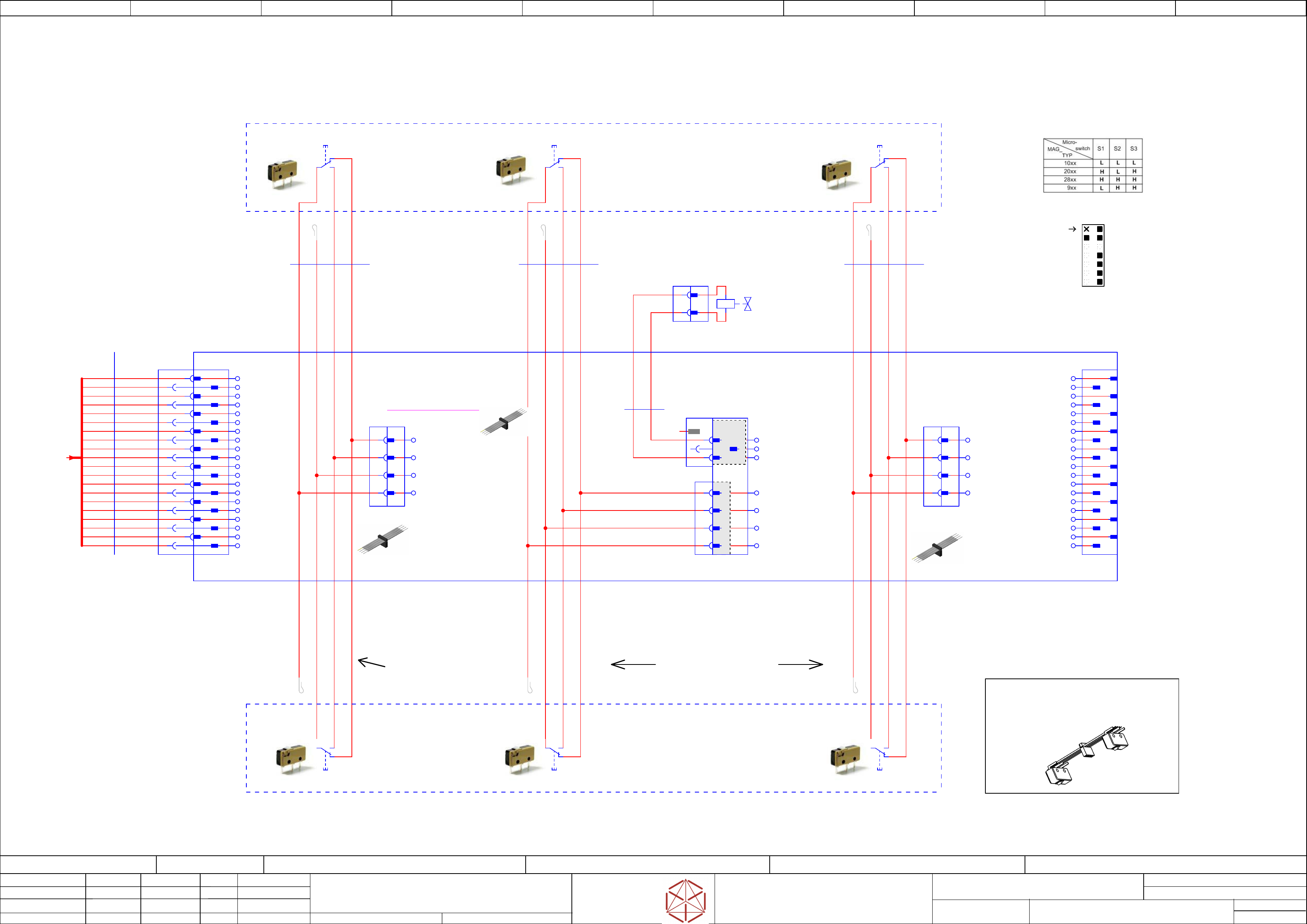
Function: Nozzle-changer
==NC=TX+short/68
drawing number:
03103649-010401LE3
Nozzle-changer
Nozzle-changer
Nozzle-changer
Nozzle-changer
GmbH & Co KG
ASM
Assembly Systems
Copyright reserved
Ed.
Original
Pingist
Date
Date
Modification
Appr
01.12.2016
Name
Version: Series from
V
ersion: S
eries f
r
om
V
ersion: Series from
Version: Series from
2016/Q4 TA500
2016/Q4 TA500
2016/Q4 TA500
2016/Q4 TA500
starting MC-Nr
.: TA500 2016/Q4 G. Pingist
1
2
3
4
-X3
-X3
-X3
-X3
DGND
SWITCH_VOLTAGE
M3C
M4C
1
2
3
4
-X4
-X4
-X4
-X4
DGND
SWITCH_VOLTAGE
M3A
M4A
03069327-xx
03069327-xx
03069327-xx
03069327-xx
03069327-xx
03069327-
xx
03069327-xx
03069327-xx
03069327-xx
03069327-
xx
03069327-xx
03069327-xx
1
20
10
2
3
4
5
6
7
8
9
11
12
13
14
15
16
17
18
19
Switch unit CPx
Switch unit CPx
Swi
tch unit CPx
Switch unit CPx
03072040-xx
03072040-xx
03072040-xx
03072040-xx
(see Note 1)
(see Note 1)
(see Note 1)
(see Note 1)
X6 Pin 8, 10, 12, 14
X6 Pin 8, 10, 12, 14
X6 Pin 8, 10, 12, 14
X6 Pin 8, 10, 12, 14
logical connector X5 Pin 1, 2, 3, 4
logical connector X5 Pin 1, 2, 3, 4
logical connector X5 Pin 1, 2, 3, 4
logical connector X5 Pin 1, 2, 3, 4
Main-PCB CPx cplt. 03069324-
xx
Main-PCB CPx cplt. 03069324-xx
Main-PCB CPx cplt. 03069324-xx
Main-PCB CPx cpl
t. 03069324-xx
NC
NC
NC
NCNO
NO
NO
NOCO
CO
CO
CO NC
NC
NC
NCNO
NO
NO
NOCO
CO
CO
CO NC
NC
NC
NCNO
NO
NO
NOCO
CO
CO
CO
NC
NC
NC
NCNO
NO
NO
NOCO
CO
CO
CO NC
NC
NC
NCNO
NO
NO
NOCO
CO
CO
CO NC
NC
NC
NCNO
NO
NO
NOCO
CO
CO
CO
Switch unit CPx
Switch unit CPx
Swi
tch unit CPx
Switch unit CPx
03072040-xx (see Note 1)
03072040-xx (see Note 1)
03072040-xx (see Note 1)
03072040-xx (see Note 1)
Note 1:
Note 1:
Note 1:
Note 1:
Switch unit CPx _ 03072040-xx
Switch unit CPx _ 03072040-xx
S
witch unit CPx _ 03072040-xx
Switch unit CPx _ 03072040-xx
> Flat ribbon cable with IDC-Socket _ 03069327-xx
> Flat ribbon cable with IDC-Sock
et _ 03069327-xx
> Flat ribbon cable with IDC-Socket _ 03069327-xx
> Flat ribbon cable with IDC-Socket _ 03069327-xx
> Microswith _ 03019563-xx
> Microswith _ 03019563-xx
> Microswi
th _ 03019563-xx
> Microswith _ 03019563-xx
Microswitch
Microswitch
Microswitch
Micr
oswitch
Microswitch
Microswitch
Microswitch
Micr
oswitch
not used
1
2
3
4
5
6
7
8
9
10
-X1
-X1
-X1
-X1
input
input
input
input
11
12
13
14
15
16
17
18
19
20
-X1.A2
-
X1.A2
-
X1.A2
-
X1.A2
1
2
3
4
5
6
7
8
9
10
11
12
13
14
15
16
17
18
19
20
1
-X3
-X3
-X3
-X3
2
3
4
-X5
-X5
-X5
-X5
1
2
3
4
-X4
-X4
-X4
-X4
1
2
3
4
-X2
-X2
-X2
-X2
2
3
4
1
2
-X1
2
2
2
2
3
3
3
3
4
4
4
4
8
8
8
8
10
10
10
10
-X6
-
X6
-
X6
-
X6
12
12
12
12
14
14
14
14
1
1
1
1
5
6
7
9
11
13
Key1
1
3
4
5
6
7
8
9
10
11
12
13
14
2
1
-X2
-X2
-X2
-X2
output
output
output
output
EARTH
SWITCH_VOLTAGE
NC
DGND
--
NC
M5A
M6A
M5B
M6B
M5C
M6C
P24V
NC
15
17
19
16
18
20
NC
NC
NC
NC
NC
EARTH
Key
X6
X6
X6
X6
1
14
2
3 4
5 6
7 8
9 10
11 12
13
Note 2
Note 2
Note 2
Note 2
Pin Header
Pin Header
Pin Header
Pin Header
Front View
Fr
ont View
Front View
Front View
NC
DGND / BK
SW_VALVE / RD
DGND
SWITCH_VOLTAGE
M3B
M4B
03069337-020101LE3
Nozzle changer (NC) base structure CPx/all cpl., short 03103649-xx
Nozzle changer (NC) base structure CPx/all cpl., short 03103649-xx
Nozzle changer (NC) base structure CPx/all cpl., short 03103649-xx
Nozzle changer (NC) base structure CPx/all cpl., short 03103649-xx
-nc
-nc
-nc
-nc
-nc
-nc
EARTH
P24V
SWITCH_VOLTAGE
SW_VALVE
DGND
Status_PCB1
Status_PCB2
M3A
M4A
M3B
4x AWG 28 / Socket: IDS-04-G
Flat ribbon cable with IDC-Socket
03069327
03069327
03069327
03069327 -01
-01
-01
-01
-W3-MAG2_4
-W3-MAG2_4
-W3-MAG2_4
-W3-MAG2_4
YEORRDBR
4x AWG 28 / Socket: IDS-04-G
Flat ribbon cable with IDC-Socket
03069327
03069327
03069327
03069327 -01
-01
-01
-01
-W2-MAG2_4
-W2-MAG2_4
-W2-MAG2_4
-W2-MAG2_4
YEORRDBR
4x AWG 28 / Socket: IDS-04-G
Flat ribbon cable with IDC-Socket
03069327
03069327
03069327
03069327 -01
-01
-01
-01
-W1-MAG2_4
-W1-MAG2_4
-W1-MAG2_4
-W1-MAG2_4
YEORRDBR
-MAG4
Magazine 4
Magazine 4
Magazine 4
Magazine 4
==OV+NC/23.5
-MAG2
Magazine 2
Magazine 2
Magazine 2
Magazine 2
==OV+NC/23.5
-A2
-A2
-A2
-A2
PCB_Sub-pcb CPx cpl.
PCB_Sub-pcb CPx cpl.
PCB_Sub-pcb CPx cpl.
PCB_Sub-pcb CPx cpl.
03069337-0201
03069337-0201
03069337-0201
03069337-0201
==OV+NC/23.5
M4B
M3C
M4C
M5A
M6A
M5B
M6B
M5C
M6C
EARTH
DGND
DGND
DGND
DGND
NC
NC
NC
NC
SW_VALVE
SW_VALVE
SW_VALVE
SW_V
ALVE
DGND
DGND
DGND
DGND
SWITCH_VOLTAGE
SWITCH_VOLTAGE
SWITCH_VOL
TAGE
SWITCH_VOLTAGE
M3B
M3B
M3B
M3B
M4B
M4B
M4B
M4B
x1
x2
-Y1
-Y1
-Y1
-Y1
NC-clamp
V
alve SYJ3143
00334200
==FLUID+/103.8 ==OV+NC/23.7
-X1
2
1
86 mm
2x0,25
SY100-68-A-10
00334212
00334212
00334212
00334212 -01
-01
-01
-01
-W1
-W1
-W1
-W1
BKRD
164 mm
20x0,057
Flat ribbon cable
03072807
03072807
03072807
03072807
-02
-02
-02
-02
-W1
-W1
-W1
-W1
2
1
4
-S3
-S3
-S3
-S3
Swi
tch_M4C
S
witch_M4C
Switch_M4C
S
witch_M4C
Microswitch
XCH 10-81
03019563
2
1
4
-S2
-S2
-S2
-S2
Swi
tch_M4B
S
witch_M4B
Switch_M4B
S
witch_M4B
Microswitch
XCH 10-81
03019563
2
1
4
-S1
-S1
-S1
-S1
Swi
tch_M4A
S
witch_M4A
Switch_M4A
S
witch_M4A
Microswitch
XCH 10-81
03019563
2
1
4
Microswitch
XCH 10-81
03019563
-S3
-S3
-S3
-S3
Swi
tch_M3C
S
witch_M3C
Switch_M3C
S
witch_M3C
2
1
4
Microswitch
XCH 10-81
03019563
-S2
-S2
-S2
-S2
Swi
tch_M3B
S
witch_M3B
Switch_M3B
S
witch_M3B
2
1
4
Microswitch
XCH 10-81
03019563
-S1
-S1
-S1
-S1
Swi
tch_M3A
S
witch_M3A
Switch_M3A
S
witch_M3A
-Sub_PCB1
/67.9
Sheet
Size DIN A2
electric_schematic_TX
electric_schematic_TX
electric_schematic_TX
electric_schematic_TX
90012154-010301LE3
Replaced by
Tape cutter
Tape cutter
Tape cutter
Tape cutter
Replaced by
69
Weitergabe sowie Vervielfältigung dieser Unterlage, Verwertung und
Mitteilung des Inhalts nicht gestattet, soweit nicht ausdrücklich zugestanden.
Proprietary Data, company confidential.
All rights reserved
Copying of this document, giving it to others and the use or
communication of the contents thereof, are forbidden without express authority.
Doc. No.
0 1 2 3 4 5 6 7 8 9
Privileged business information.
Do not release
Offenders are liable to payment of damages. All rights are reserved in the
event of the grant or the registration of a utility model or design.
Zuwiederhandlungen verpflichten zu Schadenersatz. Alle Rechte vorbehalten,
insbesondere für den Fall der Patenterteilung oder GM-Eintragung vorbehalten.
Page:
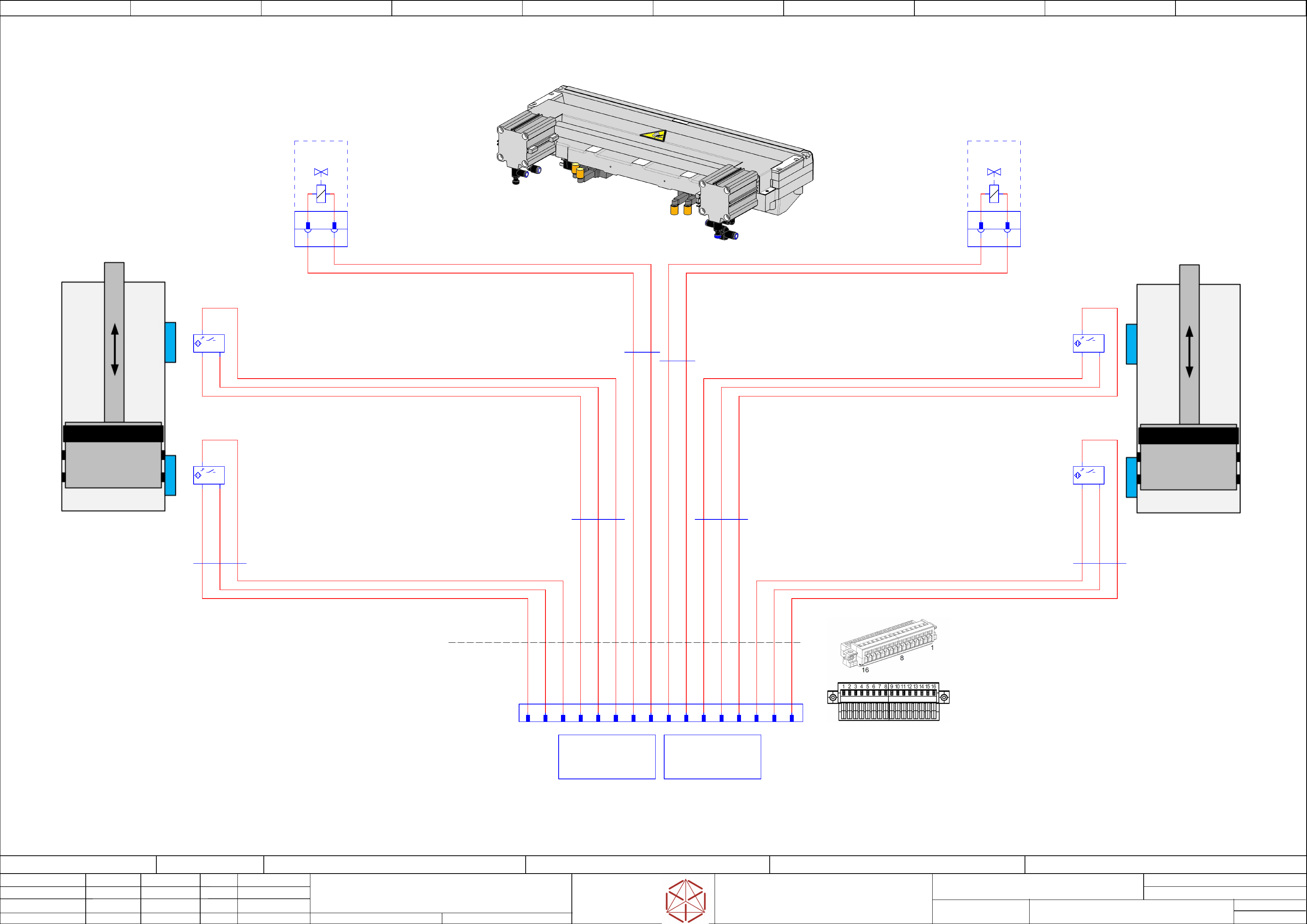
Function: Tape-cutter
==TC=TX/69
drawing number:
03066690-10201LX3
Tape_Cutter
T
ape_Cut
ter
T
ape_Cut
ter
T
ape_Cutter
GmbH & Co KG
ASM
Assembly Systems
Copyright reserved
Ed.
Original
Pingist
Date
Date
Modification
Appr
01.12.2016
Name
Version: Series from
V
ersion: S
eries f
r
om
V
ersion: Series from
Version: Series from
2016/Q4 TA500
2016/Q4 TA500
2016/Q4 TA500
2016/Q4 TA500
starting MC-Nr
.: TA500 2016/Q4 G. Pingist
Plag X1
Valve 2 (left)
Cylinder 2
Plag X2
Valve 1 (right)
Cylinder 1
Cylinder 2
(left)
-X1
-X1
-X1
-X1
1 2
-X1
-X1
-X1
-X1
1 2
Cylinder 1
(right)
-X2
-X2
-X2
-X2
1 2
WAGO
Self-adhesive marking strips
Ordering Code:
210-332/350-202
WAGO
Male connector with fixing flange, 16 pole
Ordering Code:
734-316/019-000
-X2
-X2
-X2
-X2
1 2
Tape cutter
Tape cutter
Tape cutter
T
ape cutter
03066690-0201
03066690-0201
03066690-0201
03066690-0201
-X1*h
-X1*h
-X1*h
-X1*h
1
S2+
2
S2-
3
S2 Output
4
S1+
5
S1-
6
S1 Output
7
X1+
8
X1-
9
X2+
10
X2-
11
S3+
12
S3-
13
S3 Output
14
S4+
15
S4-
16
S4 Output
Cable_set_complete
TN: 03063590
SMC-Ventil
SY5120-5LOU-01F-0
Valve+
Valve-
-Y2
-Y2
-Y2
-Y2
Valv
e 2 (left)
Cylinder 2
00328981
==FLUID/103.0 ==OV+TC/24.2
1
3
2
-S1
-S1
-S1
-S1
SMC
D-F7P
Proximity Switch S1
"Extended" position
+ -
1
3
2
-S2
-S2
-S2
-S2
SMC
D-F7P
Pro
ximity Switch S2
"Retracted" position
+ -
1
3
2
-S3
-S3
-S3
-S3
SMC
D-F7P
Proximity Switch S3
"Extended" position
+ -
1
3
2
-S4
-S4
-S4
-S4
SMC
D-F7P
Pro
ximity Switch S4
"Retracted" position
+ -
450 mm
3x0,2
D-F7P
03067072
03067072
03067072
03067072 -01
-01
-01
-01
-W1.1
-
W1.1
-W1.1
-W1.1
BN BU BK
600 mm
2x
SY100-68-A-6
03051735
03051735
03051735
03051735 -01
-01
-01
-01
-W1.4
-W1.4
-W1.4
-W1.4
RD BK
450 mm
3x0.2
D-F7P
03067072
03067072
03067072
03067072 -01
-01
-01
-01
-W1.6
-W1.6
-W1.6
-W1.6
BN BU BK
600 mm
2x
SY100-68-A-6
03051735
03051735
03051735
03051735 -01
-01
-01
-01
-W1.3
-
W1.3
-W1.3
-W1.3
RD BK
SMC-Ventil
SY5120-5LOU-01F-0
Valve+
Valve-
-Y1
-Y1
-Y1
-Y1
Valv
e (right)
Cylinder 1
00328981
==FLUID/103.2 ==OV+TC/24.7
450 mm
3x0,2
D-F7P
03067072
03067072
03067072
03067072 -01
-01
-01
-01
-W1.2
-
W1.2
-
W1.2
-
W1.2
BUBN BK
450 mm
3x0.2
D-F7P
03067072
03067072
03067072
03067072 -01
-01
-01
-01
-W1.5
-
W1.5
-
W1.5
-
W1.5
BN BU BK
==COTi+Loc1-TC
==COTi+Loc1-TC
==COTi+Loc1-
TC
==COTi+Loc1-TC
Tape cutter
Tape cutter
Tape cutter
Tape cutter
03066690-02
==COTi+Loc1/62.0
==COTi+Loc2-TC
==COTi+Loc2-TC
==COTi+Loc2-
TC
==COTi+Loc2-TC
Tape cutter
Tape cutter
Tape cutter
Tape cutter
03066690-02
==COTi+Loc2/65.0
Sheet
Size DIN A2
electric_schematic_TX
electric_schematic_TX
electric_schematic_TX
electric_schematic_TX
90012154-010301LE3
Replaced by
Motor-Y
Motor-Y
Motor-Y
Motor-Y
Replaced by
70
Weitergabe sowie Vervielfältigung dieser Unterlage, Verwertung und
Mitteilung des Inhalts nicht gestattet, soweit nicht ausdrücklich zugestanden.
Proprietary Data, company confidential.
All rights reserved
Copying of this document, giving it to others and the use or
communication of the contents thereof, are forbidden without express authority.
Doc. No.
00 01 02 03 04 05 06 07 08 09
Privileged business information.
Do not release
Offenders are liable to payment of damages. All rights are reserved in the
event of the grant or the registration of a utility model or design.
Zuwiederhandlungen verpflichten zu Schadenersatz. Alle Rechte vorbehalten,
insbesondere für den Fall der Patenterteilung oder GM-Eintragung vorbehalten.
Page:
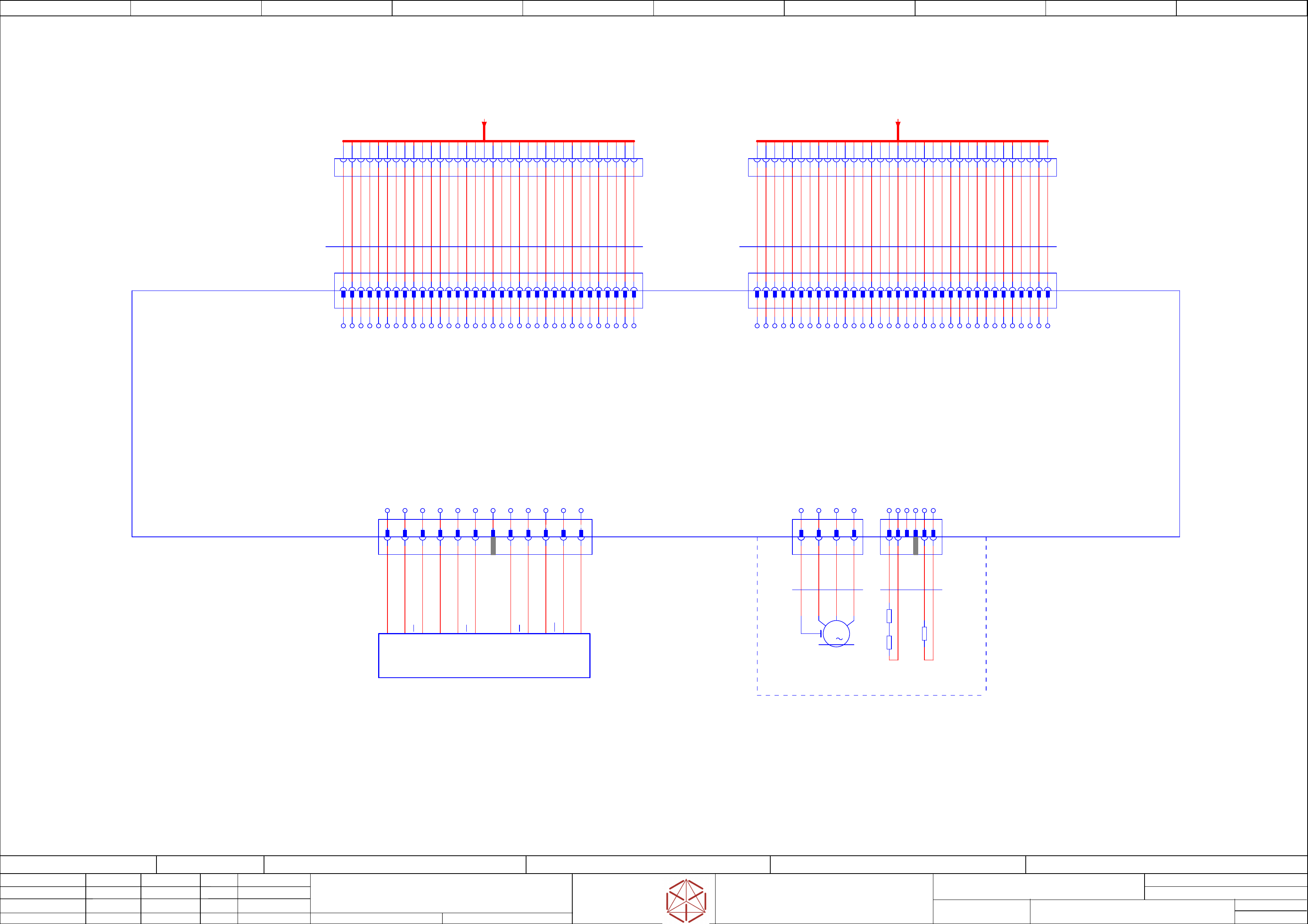
Function: Gantry
==GA=TX+GA1/70
drawing number:
90011922-010101LE3
Gantry 1
Gantry 1
Gantry 1
Gantry 1
GmbH & Co KG
ASM
Assembly Systems
Copyright reserved
Ed.
Original
Pingist
Date
Langer D.
Date
Modification
Appr
01.12.2016
Name
Version: Series from
V
ersion: S
eries f
r
om
V
ersion: Series from
Version: Series from
2016/Q4 TA500
2016/Q4 TA500
2016/Q4 TA500
2016/Q4 TA500
starting MC-Nr
.: TA500 2016/Q4 G. Pingist
-X1
-X1
-X1
-X1
Tr
ailing cable
Trailing cable
T
railing cable
Trailing cable
Y motor
Y motor
Y motor
Y motor
1
2
3
4
5
6
7
8
9
10
11
12
13
14
15
16
17
18
19
20
21
22
23
24
27
25
26
28
29
30
31
32
33
34
2
4
6
8
10
12
14
16
18
20
22
24
26
28
30
32
3
5
7
9
11
13
15
19
21
23
25
27
29
31
33
1
34
17
-X2
-X2
-X2
-X2
Tr
ailing cable
Trailing cable
T
railing cable
Trailing cable
Y motor
Y motor
Y motor
Y motor
1
2
3
4
5
6
7
8
9
10
11
12
13
14
15
16
17
18
19
20
21
22
23
24
27
25
26
28
29
30
31
32
33
34
2
4
6
8
10
12
14
16
18
20
22
24
26
28
30
32
3
5
7
9
11
13
15
19
21
23
25
27
29
31
33
1
34
17
-X1.GI
-X1.GI
-X1.GI
-X1.GI
1
2
3
4
5
6
7
8
9
10
11
12
13
14
15
16
17
18
19
20
21
22
23
24
26
28
29
30
31
33
25
27
32
34
-X1.TI
-X1.TI
-X1.TI
-X1.TI
1
2
3
4
5
6
7
8
9
10
11
12
13
14
15
16
17
18
19
20
21
22
23
24
26
28
29
30
31
33
25
27
32
34
-X2.GI
-X2.GI
-X2.GI
-X2.GI
1
2
3
4
5
6
7
8
9
10
11
12
13
14
15
16
17
18
19
20
21
22
23
24
26
28
29
30
31
33
25
27
32
34
-X2.TI
-X2.TI
-X2.TI
-X2.TI
1
2
3
4
5
6
7
8
9
10
11
12
13
14
15
16
17
18
19
20
21
22
23
24
26
28
29
30
31
33
25
27
32
34
Gantry 1
1 2 3 5
-X4_b
-X4_b
-X4_b
-X4_b
1 2 3 4
-X3_b
-
X3_b
-X3_b
-X3_b
-GI
-GI
-GI
-GI
Gantry 1
Gantry-Interface 1
Gantry-Interface 1
Gantry
-Interface 1
Gantry-Interface 1
03116149
SCREEN
YMOTORU
YMOTORU
YMOTORU
YMOTORV
YMOTORV
YMOTORV
YMOTORW
YMOTORW
YMOTORW
SCREEN
YTEMPSENS
GND
YTRACKN
YTRACKBN
GND
YTRACKA
SCREEN
YMOTORU
YMOTORU
YMOTORU
YMOTORV
YMOTORV
YMOTORV
YMOTORW
YMOTORW
YMOTORW
SCREEN
YERROR
YTRACKNN
GND
YTRACKB
YTRACKAN
SCREEN
SCREEN
YMOTORU
YMOTORU
YMOTORU
YMOTORV
YMOTORV
YMOTORV
YMOTORW
YMOTORW
YMOTORW
SCREEN
P24V
GND
GND
GND
GND
GND
SCREEN
YMOTORU
YMOTORU
YMOTORU
YMOTORV
YMOTORV
YMOTORV
YMOTORW
YMOTORW
YMOTORW
SCREEN
P24V
GND
GND
GND
GND
SCREEN
1 2 3 4
Y axis
Y axis
Y axis
Y axis
Temp. sensor PTC
Temp. sensor PTC
Temp
. sensor PTC
Temp. sensor PTC
-X13
-X13
-X13
-X13
1 2 3 4 5 6 7 8 9 1110 12
Encoder signals Yaxis
Encoder signals Yaxis
Encoder signals Yaxis
Encoder signals Yaxis
-X11
-
X11
-X11
-X11
1 2 3 4
Y axis
Motor/Power
-X12
-X12
-X12
-X12
SCREEN
Y Motor_U
Y Motor_V
Y Motor_W
GND
PTCY
NC
KEY
SCREEN
YTRACKA
YTRACKAN
GND
YTRACKB
YTRACKBN
KEY
YTRACKN
YTRACKNN
P5V
Y ERROR 5V
NC
1590 mm
34x0,14
Flat cable
03112251
03112251
03112251
03112251
-W1
-W1
-W1
-W1
1
2
3
4
5
6
7
8
9
10
11
12
13
14
15
16
17
18
19
20
21
22
23
24
25
26
27
28
29
30
31
32
33
34
1560 mm
34x0,14
Flat cable
03112252
03112252
03112252
03112252
-W2
-W2
-W2
-W2
1
2
3
4
6
7
8
9
10
11
12
13
14
15
16
17
18
19
20
21
22
23
24
25
26
27
28
29
30
31
32
33
34
NC
NC
5 6
-X11.GI
-X11.GI
-X11.GI
-X11.GI
1 2 3 4 5 6 8 9 10
5
12
T1 YE
GND WH
T2 PK
Shield WH/GN
T2 RD
+5V BK
US BU
RI BN
Test TR (transp.)
RI GY
T1 GN
03094996
Scanning head MS 22.84, Y axis (1020mm)
Scanning head MS 22.84, Y axis (1020mm)
Scanning head MS 22.84, Y axis (1020mm)
S
canning head MS 22.84, Y axis (1020mm)
Gantry 1
-UY1
-UY1
-UY1
-UY1
1 2 651 2 3 4
03095097
Linear motor primary Y axis
Linear motor primary Y axis
Linear motor primary Y axis
Linear motor primary Y axis
Gantry 1
-MY1
-MY1
-MY1
-MY1
BN
-W2
Temp
-W1
Power
Phase C
Phase B
Phase A
GND
3
M
WH
-SNM115.1
Temp_Sens
PHASE 1
YE
GN
-SNM115.2
Temp_Sens
PHASE 2
RD
WH
GN
BK
-PT100
not used
+
-
[Trailing interface]
==GA1+-X1.TI1
==CH+GA-TI1-X1:1 ==CH+GA/55.01
[Trailing interface]
==GA1+-X2.TI1
==CH+GA-TI1-X2:1 ==CH+GA/55.05
11
7
KEY
4
KEY