Detailed Circuit Diagrams Folder.pdf - 第139页
Sheet Size DIN A2 electric_schematic_TX electric_schematic_TX electric_schematic_TX electric_schematic_TX 90012154-010301LE3 Replaced by P ower and CAN Bus- A1 P ower and CAN Bus- A1 P ower and CAN Bus- A1 P ower and CAN…
Sheet
Size DIN A2
electric_schematic_TX
electric_schematic_TX
electric_schematic_TX
electric_schematic_TX
90012154-010301LE3
Replaced by
Power and CANbus wiring config to TX
Power and CANbus wiring config to TX
Power and CANbus wiring config to TX
Power and CANbus wiring config to TX
Replaced by
132
Weitergabe sowie Vervielfältigung dieser Unterlage, Verwertung und
Mitteilung des Inhalts nicht gestattet, soweit nicht ausdrücklich zugestanden.
Proprietary Data, company confidential.
All rights reserved
Copying of this document, giving it to others and the use or
communication of the contents thereof, are forbidden without express authority.
Doc. No.
0 1 2 3 4 5 6 7 8 9
Privileged business information.
Do not release
Offenders are liable to payment of damages. All rights are reserved in the
event of the grant or the registration of a utility model or design.
Zuwiederhandlungen verpflichten zu Schadenersatz. Alle Rechte vorbehalten,
insbesondere für den Fall der Patenterteilung oder GM-Eintragung vorbehalten.
Page:
Function: Conveyor
==CO=SC01+CO009/132
drawing number:
03122237-010301LX3
Shuttle-TX
Shut
tle-
TX
Shut
tle-
TX
Shut
tle-TX
GmbH & Co KG
ASM
Assembly Systems
Copyright reserved
Ed.
Original
Pingist
Date
Date
Modification
Appr
01.12.2016
Name
Version: Series from
V
ersion: S
eries f
r
om
V
ersion: Series from
Version: Series from
2016/Q4 TA500
2016/Q4 TA500
2016/Q4 TA500
2016/Q4 TA500
starting MC-Nr
.: TA500 2016/Q4 G. Pingist
Shuttle-TX Control Panel
Shuttle-TX Control Panel
Shut
tle-TX Control Panel
Shuttle-TX Control Panel
TX External Interfacing Connections
TX External I
nterf
acing Connections
TX External I
nterf
acing Connections
TX External I
nterfacing Connections
24V
GND (42V)
PWROK
GND (24V)
ID_DOWNSTREAM
24V
42V
PWROK
GND (42V)
ID_DOWNSTREAM
GND (24V)
42V
PEPE
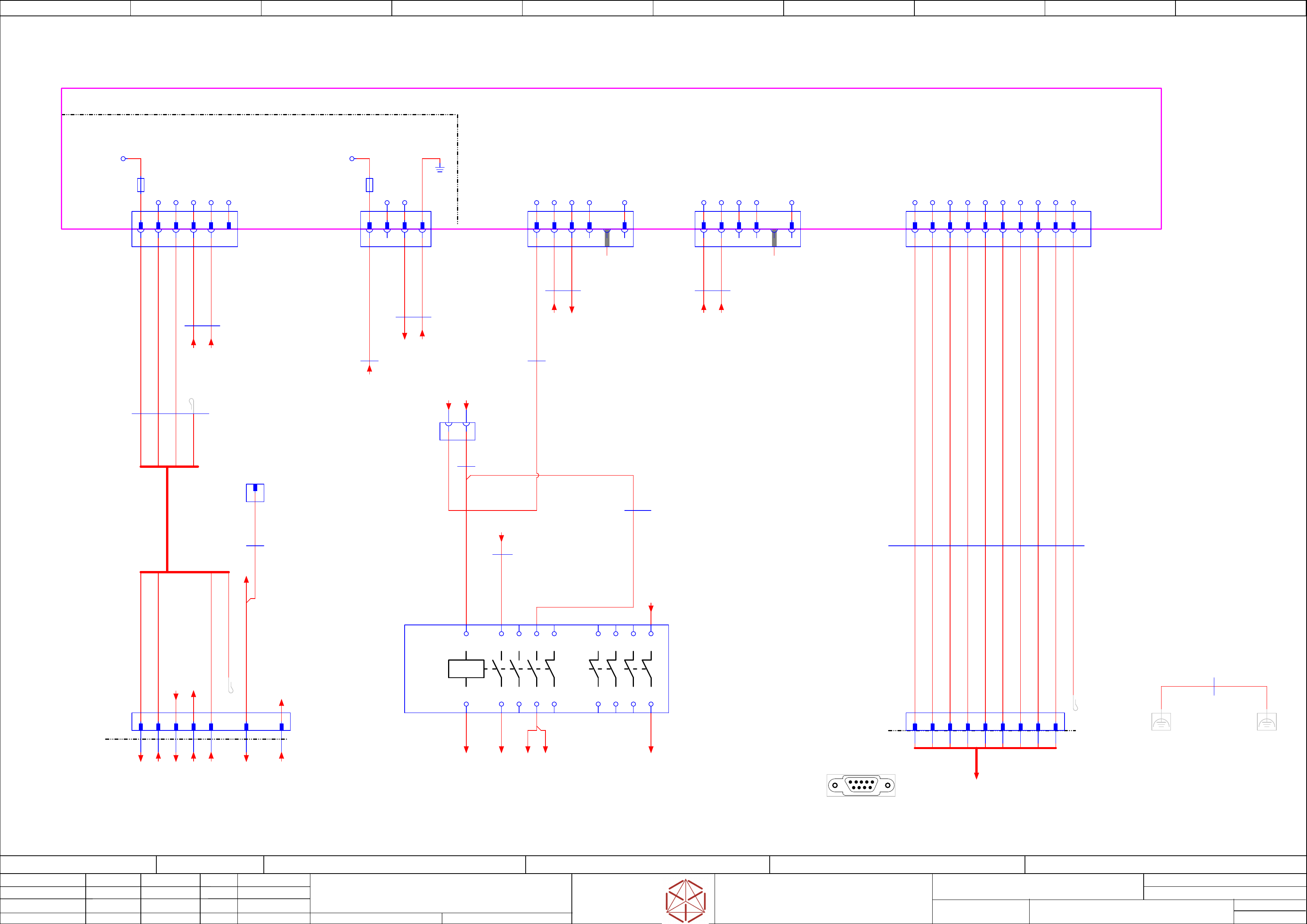
For special configurations where both Shuttle-TX are connected
For special configurations where both Shuttle-
TX are connected
For special configurations where both Shuttle-TX are connected
For special configurations where both Shuttle-TX are connected
to a single TX machine, the CAN cable (Shuttle Upstream) X1 IDC
to a single TX machine, the CAN cable (Shuttle Upstream) X1 IDC
to a single TX machine, the CAN cable (Shuttle Upstream) X1 IDC
to a single TX machine, the CAN cable (Shuttle Upstream) X1 IDC
will connect to CAN cable (Shuttle Downstream) X1* IDC.
will connect to CAN cable (Shuttle Downstream) X1* IDC.
wi
ll connect to CAN cable (Shuttle Downstream) X1* IDC.
will connect to CAN cable (Shuttle Downstream) X1* IDC.
The CAN cable (Shuttle Upstream) X52 IDC will connect to TSP420
The CAN cable (Shuttle Upstream) X52 IDC will connect to T
SP420
The CAN cable (Shuttle Upstream) X52 IDC will connect to TSP420
The CAN cable (Shuttle Upstream) X52 IDC will connect to TSP420
Shuttle Upstream.
Shuttle Upstream.
Shuttle Upstream.
Shut
tle Upstream.
The CAN cable (Shuttle Downstream) X52 IDC will connect to TSP420
The CAN cable (Shuttle Downstream) X52 IDC will connect to T
SP420
The CAN cable (Shuttle Downstream) X52 IDC will connect to TSP420
The CAN cable (Shuttle Downstream) X52 IDC will connect to TSP420
Shuttle Downstream.
Shuttle Downstream.
Shuttle Downstream.
Shut
tle Downstream.
THe CAN cable (Shuttle Downstream) X1 IDC will connect to TX machine CAN3.EXT.
THe CAN cable (Shuttle Downstream) X1 IDC will connect to TX machine CAN3.EXT
.
THe CAN cable (Shuttle Downstream) X1 IDC will connect to TX machine CAN3.EXT.
THe CAN cable (Shuttle Downstream) X1 IDC will connect to TX machine CAN3.EXT.
Terminating connector on CAN3.EXT will connect to CAN cable (Shuttle Upstream) X1* IDC
Terminating connector on CAN3.EXT will connect to CAN cable (Shuttle Upstr
eam) X1* IDC
Terminating connector on CAN3.EXT will connect to CAN cable (Shuttle Upstream) X1* IDC
Terminating connector on CAN3.EXT will connect to CAN cable (Shuttle Upstream) X1* IDC
-X52
-
X52
-
X52
-
X52
1 2 3 4 56 7 8 9
1 2 3 4 7 865
10
9
1 2 3 4 7 865 9 10
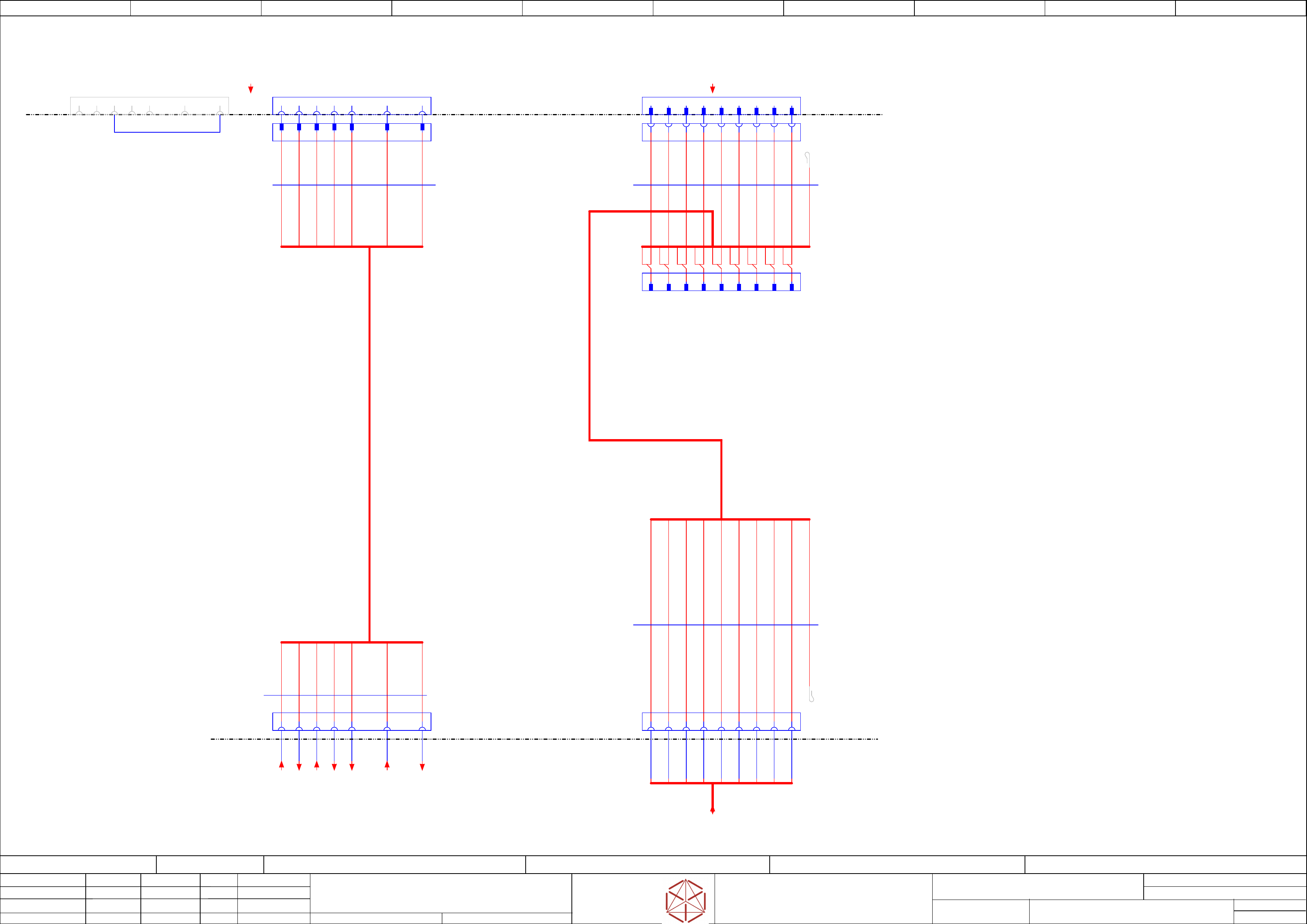
The power interface cable is connected between
The power interface cable is connected between
The power interface cable is connected between
The power interface cable is connected between
X50 (Shuttle Extension interf
ace panel)
X50 (Shuttle Extension interface panel)
X50 (Shuttle Extension interface panel)
X50 (Shut
tle Extension interface panel)
and X15.S1 (Shuttle Upstream)
and X15.S1 (Shuttle Upstream)
and X15.S1 (Shuttle Upstream)
and X15.S1 (Shut
tle Upstream)
or X15.S2 (Shuttle Downstream).
or X15.S2 (Shuttle Downstream).
or X15.S2 (Shuttle Downstream).
or X15.S2 (Shut
tle Downstream).
Shuttle Downstream
Shuttle Downstream
Shuttle Downstream
Shut
tle Downstream Shuttle Upstream
Shuttle Upstream
Shuttle Upstream
Shuttle Upstream
1 92 3 4 5 6 7 8
X15.S2 has a jumper wire between pin 9 and pin 3
X15.S2 has a jumper wire between pin 9 and pin 3
X15.S2 has a jumper wire between pin 9 and pin 3
X15.S2 has a jumper wire between pin 9 and pin 3
to indicate to Shuttle Extension
to indicate to Shut
tle Extension
to indicate to Shuttle Extension
to indicate to Shuttle Extension
that it is configur
ed as a downstream machine.
that it is configured as a downstream machine.
that it is configured as a downstream machine.
that it is configured as a downstream machine.
For single Shutlle configuration,
F
or single Shutl
le configur
ation,
F
or single Shutl
le configuration,
For single Shutlle configuration,
terminating connector on CAN3.EXT is removed
terminating connector on CAN3.EXT is removed
terminating connector on CAN3.EXT is removed
terminating connector on CAN3.EXT is removed
and connect to CAN cable X1* IDC
and connect to CAN cable X1* IDC
and connect to CAN cable X1* IDC
and connect to CAN cable X1* IDC
6
-X50
-
X50
-X50
-X50
-X15.S1
-X15.S1
-X15.S1
-X15.S1
81 2 3 4 5 7
6
-X15.*
8
6 8
1 2 3 4 5 7
1 2 3 4 5 7 9
9
9
3000 mm
3G1,0
ÖLFLEX® 150
03133550
03133550
03133550
03133550 -01
-01
-01
-01
-W21.2
-W21.2
-W21.2
-W21.2
1 2 GNYE
3000 mm
4x0,5
UNITRONIC® LiYY
03133550
03133550
03133550
03133550 -01
-01
-01
-01
-W21.1
-W21.1
-W21.1
-W21.1
BN GN YEWH
-CAN3.EXT
-CAN3.EXT
-CAN3.EXT
-CAN3.EXT
1 2 3 4 56 7 8 9
-X1
-X1
-X1
-X1
1 2 4 56 7 8 93
-X1*
-X1*
-X1*
-X1*
1 4 56 7 8 92 3
nc
nc
2950 mm
10x0.09
Flat round cable
03133551
03133551
03133551
03133551 -02
-02
-02
-02
-W22.2
-W22.2
-W22.2
-W22.2
1 2 3 4 5 6 7 8 9 10
50 mm
10x0.09
Flat round cable
03133551
03133551
03133551
03133551 -02
-02
-02
-02
-W22.1
-
W22.1
-
W22.1
-
W22.1
1 2 3 4 7 865 9 10
-X15.S2
-X15.S2
-X15.S2
-X15.S2
1 2 3 4 5
6
7
8
9
-GND42
/133.1
-PE
/133.1
-GND1
/133.1
-24V
/133.1
-42V1
/133.1
-ID_DOWNSTREAM
/133.2
-PWROK
/133.1
-CAN
/133.7
CAN3.Shuttle
==OV=TX+CH/16.9
PWR_Shuttle
==CH=TX+PS/48.3
Sheet
Size DIN A2
electric_schematic_TX
electric_schematic_TX
electric_schematic_TX
electric_schematic_TX
90012154-010301LE3
Replaced by
Power and CAN Bus- A1
Power and CAN Bus- A1
Power and CAN Bus- A1
Power and CAN Bus- A1
Replaced by
133
Weitergabe sowie Vervielfältigung dieser Unterlage, Verwertung und
Mitteilung des Inhalts nicht gestattet, soweit nicht ausdrücklich zugestanden.
Proprietary Data, company confidential.
All rights reserved
Copying of this document, giving it to others and the use or
communication of the contents thereof, are forbidden without express authority.
Doc. No.
0 1 2 3 4 5 6 7 8 9
Privileged business information.
Do not release
Offenders are liable to payment of damages. All rights are reserved in the
event of the grant or the registration of a utility model or design.
Zuwiederhandlungen verpflichten zu Schadenersatz. Alle Rechte vorbehalten,
insbesondere für den Fall der Patenterteilung oder GM-Eintragung vorbehalten.
Page:
Function: Conveyor
==CO=SC01+CO009/133
drawing number:
03122237-010301LX3
Shuttle-TX
Shut
tle-
TX
Shut
tle-
TX
Shut
tle-TX
GmbH & Co KG
ASM
Assembly Systems
Copyright reserved
Ed.
Original
Pingist
Date
Date
Modification
Appr
05.12.2016
Name
Version: Series from
V
ersion: S
eries f
r
om
V
ersion: Series from
Version: Series from
2016/Q4 TA500
2016/Q4 TA500
2016/Q4 TA500
2016/Q4 TA500
starting MC-Nr
.: TA500 2016/Q4 G. Pingist
CONTROL - POWER
CONTROL - POWER
CONTROL - POWER
CONTROL - POWER
MOTOR - POWER
MOTOR - POWER
MOTOR - POWER
MO
TOR - POWER
BN 24V
WH PWROK
GN GND(24)
YE BRK(24V)
GN GND(24)
YE BRK(24V)
WH PWROK
BN 24V
Control-unit TSP-420-IO (daughter-board)
Control-unit TSP-420-IO (daughter
-board)
Control-unit TSP-420-IO (daughter-board)
Control-unit TSP-420-IO (daughter-board)
Control-unit TSP-420-M (main-board)
Control-unit TSP-420-M (main-board)
Contr
ol-unit TSP-420-M (main-board)
Control-unit TSP-420-M (main-board)
Shuttle-TX Control Panel
Shuttle-TX Control Panel
Shut
tle-TX Control Panel
Shuttle-TX Control Panel
-A1(qb)-X52
-A1(qb)-X52
-A1(qb)-X52
-
A1(qb)-X52
Machine-Canbus-1
Machine-Canbus-1
Machine-Canbus-1
Machine-Canbus-1
Sub-D 9pol.male
Shuttle-TX Control Panel
Shuttle-TX Control Panel
Shut
tle-TX Control Panel
Shuttle-TX Control Panel
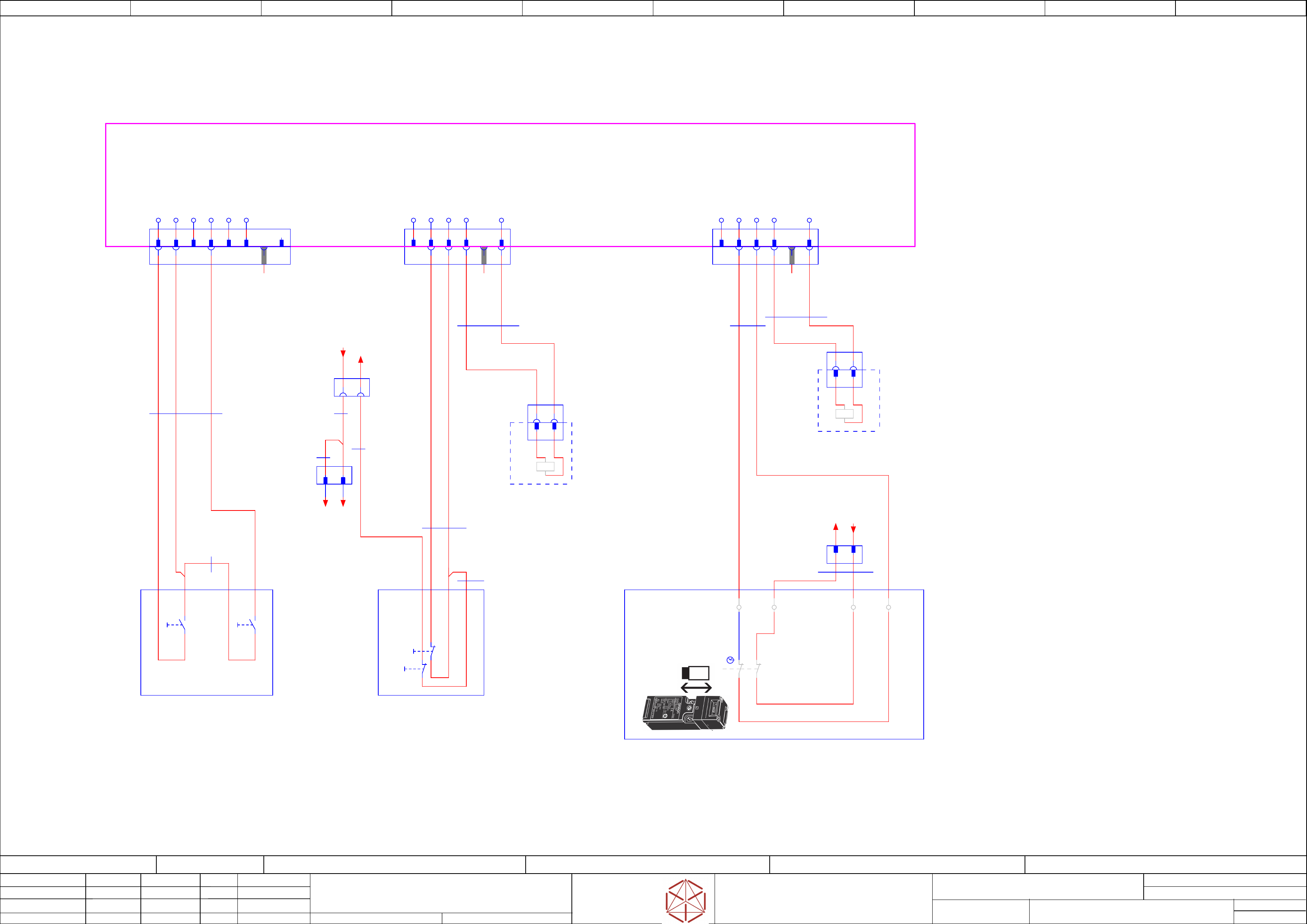
Note: Verification of Contactor
Note: Verification of Contactor
Note: Verification of Contactor
Note: V
erification of Contactor
(Spoil or connection) before power up
(Spoil or connection) before power up
(Spoil or connection) before power up
(Spoil or connection) before power up
1 2 5 76
-X50
-
X50
-X50
-X50
Conv
eyor input power
3 4 8 9
1 92 3 4 5 6 7 8
Ground cable between
Ground cable between
Ground cable between
Ground cable between
top cov
er and shuttle frame
top cover and shuttle fr
ame
top cover and shuttle frame
top cover and shuttle frame
1
2 3 4 56 7 8 9
-A1
-A1
-A1
-A1
PCB: "Lane-1"
PCB: "Lane-1"
PCB: "Lane-1"
PCB: "Lane-1"
TSP-420-
xx
03087642-
-X29
-X29
-X29
-X29
1 2 3 4 5 6
-X28
-X28
-X28
-X28
1 3 4
-X28
-X28
-X28
-X28
Mate-N-Lok
1 3 4
-X29
-X29
-X29
-X29
Mini-Mate-N-Lok
1 2 3 4 5 6
PWROK
P-BRK(24V)
GND2(24)
Pass-Trough
GND1(24)
1
2
-F2
2AT
GND(42)
1
2
-F1
6,3AT
+42V
PE
+24V
nc
2
nc
2
nc
-X46
-X46
-X46
-X46
1 3 4 6
Key
-X46
-X46
-X46
-X46
1 2 3 4 65
IN12
IN16
P24EA
OUT5
GND
2
-X47
-X47
-X47
-X47
1 3 4 6
-X47
-X47
-X47
-X47
1 2 3 4 65
IN13
IN17
P24EA
OUT7
GND
2
Key
500 mm
2x1
Single core MULTI-STANDARD SC 1
03123637
03123637
03123637
03123637
-02
-02
-02
-02
-W1.3
-W1.3
-W1.3
-W1.3
520 mm
1x1
Single core MULTI-STANDARD SC 1
03123637
03123637
03123637
03123637 -02
-02
-02
-02
-W1.5
-W1.5
-W1.5
-W1.5
-X22
-X22
-X22
-X22
1 3 7 92 4 6 85
nc
340 mm
10x0.09
Flat round cable
03123642
03123642
03123642
03123642 -01
-01
-01
-01
-W15
-W15
-W15
-W15
1 103 7 92 4 6 85
BK
-K9
-K9
-K9
-K9
Contactor
100S-C09EJ14C
03124243-
==OV_SH+/125 ==OV_SH+CO/129.5 ==OV_SH+CO/129.6
1 3 5 13A1
A2 2 4 6 14
51 61
52 62
71 81
72 82
BK
2
-X22
-X22
-X22
-X22
1 2 3 4 5 6 7 8 9 10
10
2x0,25
Einzelader Multinorm
03123637
03123637
03123637
03123637 -02
-02
-02
-02
-W1.6
-
W1.6
-
W1.6
-
W1.6
5 5
440 mm
1x1
Single core MULTI-STANDARD SC 1
03123637
03123637
03123637
03123637 -02
-02
-02
-02
-W1.4
-W1.4
-W1.4
-W1.4
600 mm
4x0,5
UNITRONIC® LiYY
03123637
03123637
03123637
03123637 -02
-02
-02
-02
-W1.1
-W1.1
-W1.1
-W1.1
BK
2x0,25
Einzelader Multinorm
03123637
03123637
03123637
03123637 -02
-02
-02
-02
-W1.8
-
W1.8
-W1.8
-W1.8
BK
GNBN WH YE
2x0,5
Single core MULTI-STANDARD SC 1
03123637
03123637
03123637
03123637 -02
-02
-02
-02
-W1.2
-
W1.2
-W1.2
-W1.2
BK
260 mm
1x0,25
Einzelader Multinorm
03123637
03123637
03123637
03123637 -02
-02
-02
-02
-W1.10
-W1.10
-W1.10
-W1.10
BK
100 mm
1x0,25
Einzelader Multinorm
03123637
03123637
03123637
03123637 -02
-02
-02
-02
-W1.11
-
W1.11
-W1.11
-W1.11
BK
1
-X90qc
-X90qc
-X90qc
-X90qc
430 mm
1x0,25
Einzelader Multinorm
03123637
03123637
03123637
03123637 -02
-02
-02
-02
-W1.9
-W1.9
-W1.9
-W1.9
BK
GNYE
Frame Stub
400 mm
1x1
Single core MULTI-STANDARD SC 1
03123637
03123637
03123637
03123637 -02
-02
-02
-02
-W1.7
-
W1.7
-W1.7
-
W1.7
GNYE
BK
-X52
-X52
-X52
-X52
-PE.TC
Shuttle top cover
-PE
Shuttle frame
100 mm
1x1
Single core MULTI-STANDARD SC 1
03151850
03151850
03151850
03151850 -01
-01
-01
-01
-W27
-W27
-W27
-W27
GNYE
NC
NC
NC
NC
NC
NC
GND_CAN
CANL
CANH
GND_CAN
-42V1
/132.2
-PWROK
/132.2
-24V
/132.2
-ID_DOWNSTREAM
/132.3
-ID_DOWNSTREAM_IN
/133.2
-ID_DOWNSTREAM_IN
/133.5
-Safety_contactor_closed
/133.4
-42V1_A1
/133.3
-P_BRK_A1
/133.4
-42V1_K9_A1
/133.3
-K9_A2
/133.3
-K9_A1_ok /134.2
-42V1_A1 /133.1
-K9_A2/133.1
-42V1_K9_A1/133.2
-Power_Enable/133.4
-Safety_contactor_closed/133.5
-Power_Enable
/133.4
-P_BRK_A1/133.1
-Safety_circuit_closed /134.2
-P24V_test /133.4
-PE_A1
/133.1
-PE_A1
/133.3
-P24V_test
/133.4
-GND1
/132.2
-GND42
/132.2
-GND42_A1
/133.3
-GND42_A1 /133.1
-PE
/132.2
-CAN
/132.5
Sheet
Size DIN A2
electric_schematic_TX
electric_schematic_TX
electric_schematic_TX
electric_schematic_TX
90012154-010301LE3
Replaced by
Control and Safety Loop wiring - A1
Control and Safety Loop wiring - A1
Control and Safety Loop wiring - A1
Control and Safety Loop wiring - A1
Replaced by
134
Weitergabe sowie Vervielfältigung dieser Unterlage, Verwertung und
Mitteilung des Inhalts nicht gestattet, soweit nicht ausdrücklich zugestanden.
Proprietary Data, company confidential.
All rights reserved
Copying of this document, giving it to others and the use or
communication of the contents thereof, are forbidden without express authority.
Doc. No.
0 1 2 3 4 5 6 7 8 9
Privileged business information.
Do not release
Offenders are liable to payment of damages. All rights are reserved in the
event of the grant or the registration of a utility model or design.
Zuwiederhandlungen verpflichten zu Schadenersatz. Alle Rechte vorbehalten,
insbesondere für den Fall der Patenterteilung oder GM-Eintragung vorbehalten.
Page:
Function: Conveyor
==CO=SC01+CO009/134
drawing number:
03122237-010301LX3
Shuttle-TX
Shut
tle-
TX
Shut
tle-
TX
Shut
tle-TX
GmbH & Co KG
ASM
Assembly Systems
Copyright reserved
Ed.
Original
Pingist
Date
Date
Modification
Appr
01.12.2016
Name
Version: Series from
V
ersion: S
eries f
r
om
V
ersion: Series from
Version: Series from
2016/Q4 TA500
2016/Q4 TA500
2016/Q4 TA500
2016/Q4 TA500
starting MC-Nr
.: TA500 2016/Q4 G. Pingist
-X44
-X44
-X44
-X44
3 4 6
Key
-X44
-X44
-X44
-X44
1 2 3 4 65
-A1
-A1
-A1
-A1
PCB: "Lane-1"
PCB: "Lane-1"
PCB: "Lane-1"
PCB: "Lane-1"
TSP-420-
xx
03087642-
/133.0
NC
IN28
P24EA
OUT10
GND
-CTRL2
-CTRL2
-CTRL2
-CTRL2
Emergency Stop Button
Emer
gency Stop Button
Emergency Stop B
utton
Emergency Stop Button
00334073
==OV_SH+CO/129.6
1070 mm
2x0.23
UNITRONIC® LiYY A
03123647
03123647
03123647
03123647 -01
-01
-01
-01
-W10.1
-W10.1
-W10.1
-W10.1
200 mm
2x0.23
UNITRONIC® LiYY A
03123840
03123840
03123840
03123840 -01
-01
-01
-01
-W11.3
-W11.3
-W11.3
-W11.3
2
-X45
-X45
-X45
-X45
1 2 3 4 65
NC
IN29
P24EA
OUT11
GND
Key
-X45
-X45
-X45
-X45
3 4 62
11
12
-S5
-S5
-S5
-S5
Safet
y switch D4NS-1BF
Saf
ety switch D4NS-1BF
Safet
y switch D4NS-1BF
Safety switch D4NS-1BF
OMRON D4NS-1BF, 2NC
03123661-
separate
separate
separate
separate
actuator
actuator
actuator
actuator
31
32
A1_in
X31
A1_out
X32
Hood_ok
X12
+24V
X11
-X90qb
-X90qb
-X90qb
-X90qb
21
1400 mm
2x0.23
UNITRONIC® LiYY A
03123840
03123840
03123840
03123840 -01
-01
-01
-01
-W11.2
-
W11.2
-W11.2
-W11.2
WH
WH
-X90qa
-X90qa
-X90qa
-X90qa
1 2
860 mm
2x0.23
UNITRONIC® LiYY A
03123647
03123647
03123647
03123647 -01
-01
-01
-01
-W10.3
-
W10.3
-W10.3
-W10.3
1500 mm
2x0.23
UNITRONIC® LiYY A
03123840
03123840
03123840
03123840 -01
-01
-01
-01
-W11.1
-W11.1
-W11.1
-W11.1
-X90qa
-X90qa
-X90qa
-X90qa
1 2
BN
-X90qb
-X90qb
-X90qb
-X90qb
1 2
-X52
-X52
-X52
-X52
1 2 4 8
Key
-X52
-X52
-X52
-X52
1 2 3 4 5 6 87
IN0
P24EA
GND
IN3
P24EA
GND
-S2
STOP
3
4
-CTRL1
-CTRL1
-CTRL1
-CTRL1
Start Stop Button
Start Stop B
utton
Start Stop Button
Start Stop B
utton
00349458-
==OV_SH+CO/129.5
1200 mm
3x0,34
UNITRONIC® LiYY A
03123646
03123646
03123646
03123646 -01
-01
-01
-01
-W9.1
-
W9.1
-
W9.1
-
W9.1
WH BN GN
WH
BN
-X90qc
-X90qc
-X90qc
-X90qc
1 2
53 6
-EM1
Electromagnet 1
Electromagnet 1
Electromagnet 1
Electromagnet 1
03136719
==OV_SH+CO/129.7
-EM2
Electromagnet2
Electr
omagnet2
Electr
omagnet2
Electr
omagnet2
03136719
==OV_SH+CO/129.8
1 2
21
-X2*
-X2*
-X2*
-X2*
-X1*
-X1*
-X1*
-X1*
WH BN
WH BN
BN
-S4
1
2
-S3
1
2
80 mm
1x0,25
Einzelader Multinorm
03123647
03123647
03123647
03123647 -01
-01
-01
-01
-W10.2
-
W10.2
-W10.2
-W10.2
BK
120 mm
1x0,25
Einzelader Multinorm
03123647
03123647
03123647
03123647 -01
-01
-01
-01
-W10.4
-W10.4
-W10.4
-W10.4
1100 mm
1x0,25
Einzelader Multinorm
03123647
03123647
03123647
03123647 -01
-01
-01
-01
-W10.6
-W10.6
-W10.6
-W10.6
BK
BK
1
80 mm
1x0,25
Einzelader Multinorm
03123647
03123647
03123647
03123647 -01
-01
-01
-01
-W10.5
-W10.5
-W10.5
-W10.5
BK
5
7 5
80 mm
1x0,25
Einzelader Multinorm
03123646
03123646
03123646
03123646 -01
-01
-01
-01
-W9.2
-
W9.2
-W9.2
-W9.2
BK
1
-S1
START
3
4
-K9_A1_ES_ok
/134.6
-K9_A1_C_ok
/134.2
-K9_A1_ES_ok
/134.2
-Safety_circuit_closed /133.3
-K9_A1_ok /133.3
-K9_A1_C_ok
/134.6