Detailed Circuit Diagrams Folder.pdf - 第45页
Sheet Size DIN A2 electric_schematic_TX electric_schematic_TX electric_schematic_TX electric_schematic_TX 90012154-010301LE3 Replaced by Low V oltage supply -Fusing Low V oltage supply -Fusing Low V oltage supply -Fusing…
Sheet
Size DIN A2
electric_schematic_TX
electric_schematic_TX
electric_schematic_TX
electric_schematic_TX
90012154-010301LE3
Replaced by
DC 300 V
DC 300 V
DC 300 V
DC 300 V
Replaced by
38
Weitergabe sowie Vervielfältigung dieser Unterlage, Verwertung und
Mitteilung des Inhalts nicht gestattet, soweit nicht ausdrücklich zugestanden.
Proprietary Data, company confidential.
All rights reserved
Copying of this document, giving it to others and the use or
communication of the contents thereof, are forbidden without express authority.
Doc. No.
0 1 2 3 4 5 6 7 8 9
Privileged business information.
Do not release
Offenders are liable to payment of damages. All rights are reserved in the
event of the grant or the registration of a utility model or design.
Zuwiederhandlungen verpflichten zu Schadenersatz. Alle Rechte vorbehalten,
insbesondere für den Fall der Patenterteilung oder GM-Eintragung vorbehalten.
Page:
Function: Power Supply TX, switched mode
==PS005=TX+ELS/38
drawing number:
03119265-030101LE3
Power_supply electric_slide_in
P
ower_supply electric_sl
ide_in
P
ower_supply electric_sl
ide_in
P
ower_supply electric_slide_in
GmbH & Co KG
ASM
Assembly Systems
Copyright reserved
Ed.
Original
Pingist
Date
Date
Modification
Appr
01.12.2016
Name
Version: Series from
V
ersion: S
eries f
r
om
V
ersion: Series from
Version: Series from
2016/Q4 TA500
2016/Q4 TA500
2016/Q4 TA500
2016/Q4 TA500
starting MC-Nr
.: TA500 2016/Q4 G. Pingist
P_GND_2
P_GND_1
Discharge
Control
Diagnostic
Master
24V
5 V
Bus Master +
Controller -->
discharge logic
CAP value detection
I/O
ADC:
U, I
RS485
driver
4
Overload
DC ok
GND
GND
RS485
driver
-X2
-X2
-X2
-X2
Diagnostic Interf
ace
1 2 3 4
-X2
-X2
-X2
-X2
DC-P
ower out
160V/300V
1 2 3 4
-X102.ELS
-X102.ELS
-X102.ELS
-X102.ELS
primary-f
eed
3x400V AC / PE
MATE-N-LOK Socket 4-pin
TYCO.350780-1
D+/D-
5V/GND
Drill
1
2 3 4 5 6 87
RJ45
Diagnostic
Diagnostic
Diagnostic
Diagnostic
Master
Master
Master
Master
-X0
-X0
-X0
-X0
GND
RS485_OUT_NINV
RS485_OUT_INV
+24V
RS485_IN_NINV
RS485_IN_INV
+24V
GND
1 2 3 4 5 6 7 8
RJ45
-X14.DI
-X14.DI
-X14.DI
-
X14.DI
-X0.CAP1
-X0.CAP1
-X0.CAP1
-X0.CAP1
RJ45
Diagnostic Master
1 2 3 4 5 6 7 8
RS485_IN_NINV
GND 1
+24V 2
RS485_IN_INV
GND 2
+24V 1
RS485_OUT_NINV
RS485_OUT_INV
+24V 1
RS485_OUT_INV
RS485_OUT_NINV
GND 1
RS485_IN_NINV
RS485_IN_INV
+24V 2
GND 2
<---- Electric slide in
<---- Electric slide in
<---- Electric slide in
<---- Electric slide in
Voltage testing point
Voltage testing point
Voltage testing point
V
oltage testing point
Use for testing purpose only!
Use for testing purpose only!
Use for testing purpose only!
Use for testing purpose only!
Voltage testing point
Voltage testing point
Voltage testing point
V
oltage testing point
Use for testing purpose only!
Use for testing purpose only!
Use for testing purpose only!
Use for testing purpose only!
P_160
P_GND_1
P_300
P_160
P_GND_2
P_300
3AC 380-400V
crossover
crossover
crossover
crossover
green Label
with marked
crossover
crossover
crossover
crossover
green Label
with marked
-X1
-X1
-X1
-X1
Power DC
-Out
160V/300V
1 2 3 4 5
-X1.CAP1
-X1.CAP1
-X1.CAP1
-X1.CAP1
Power
-X3.CAP1
-X3.CAP1
-X3.CAP1
-X3.CAP1
Phoenix Mini Combicon
QT40 Diagnostic
1234
-X2.PS1
-X2.PS1
-X2.PS1
-X2.PS1
Diagnostic
1 2 3 4
-X1.PS1
-X1.PS1
-X1.PS1
-X1.PS1
Power
1 2 3 4 5
-X3
-X3
-X3
-X3
Diagnostic 1
1234
-X2.CAP1
-X2.CAP1
-X2.CAP1
-X2.CAP1
DC-P
ower out
1 2 3 4
-PS1
-PS1
-PS1
-PS1
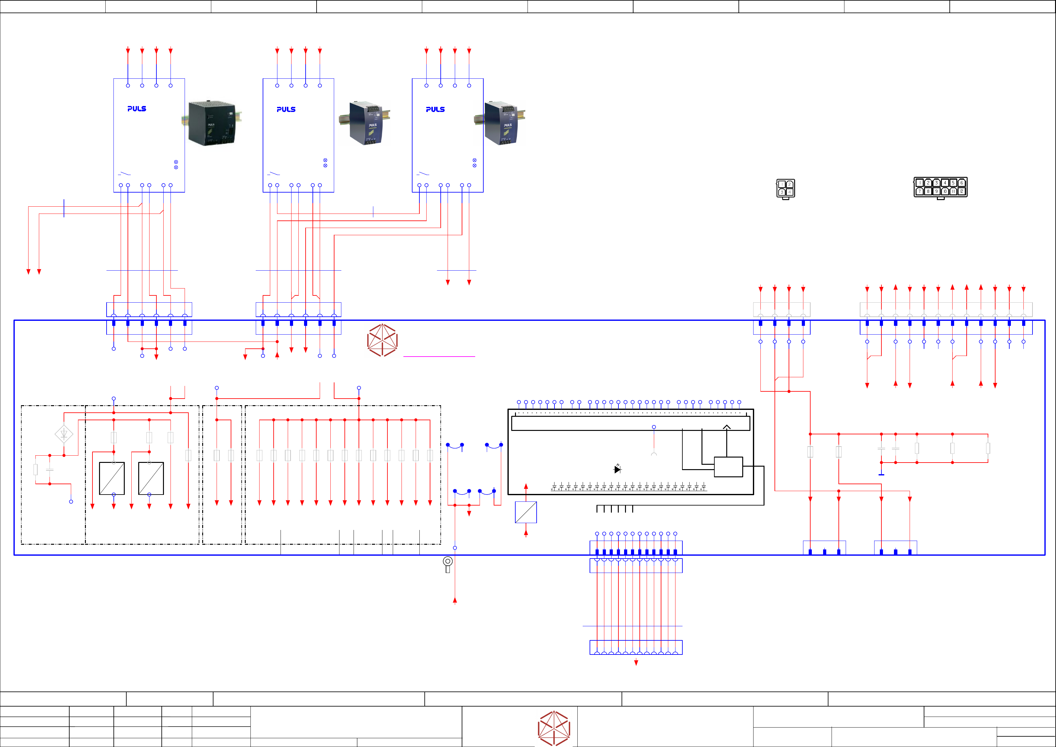
Power-supply 3AC 380-400V 1,2KW
Power-supply 3AC 380-400V 1,2KW
Power-supply 3AC 380-400V 1,2KW
P
ower-supply 3AC 380-400V 1,2KW
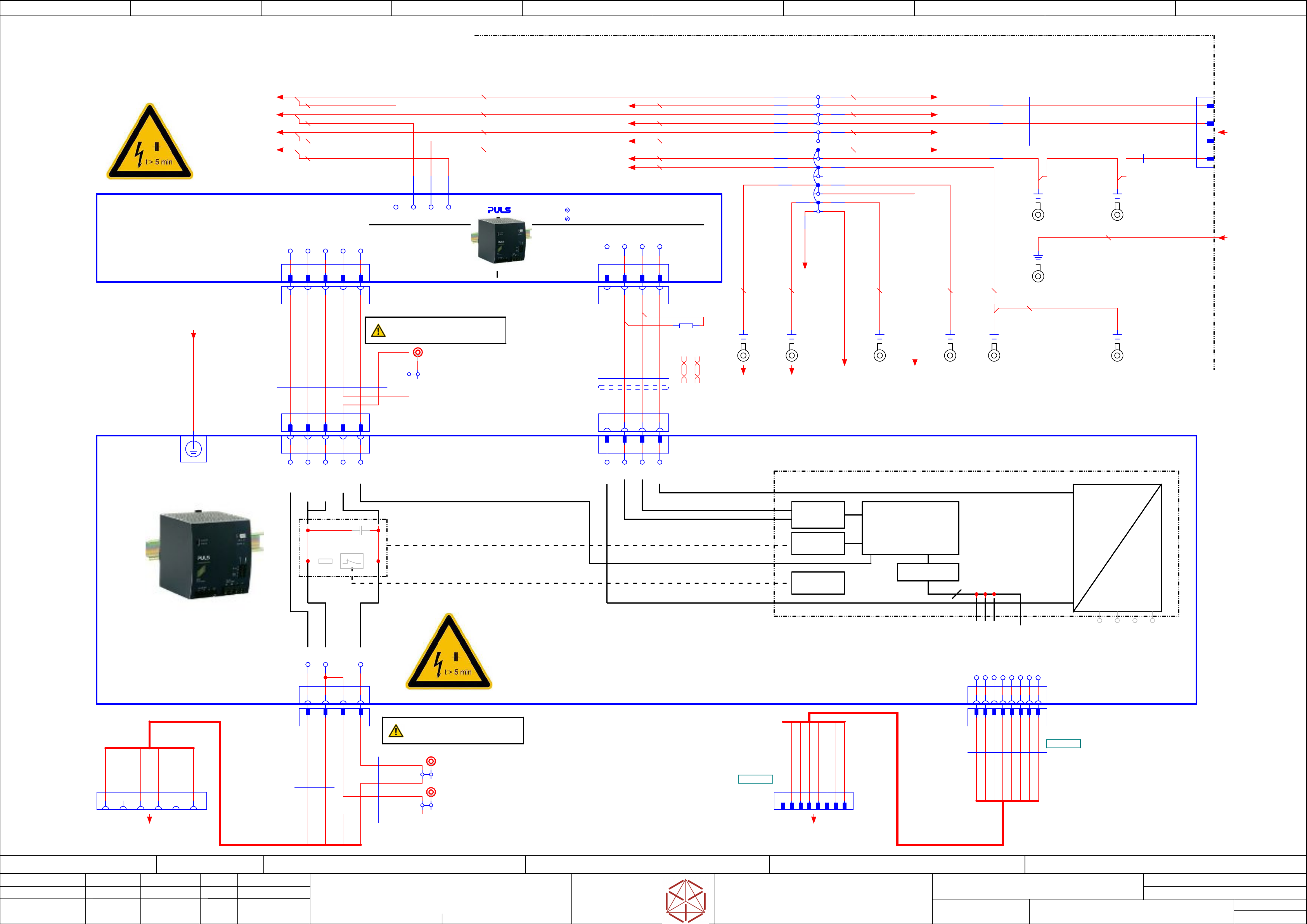
AC3~ 380-415 V/DC300 and 160 V; 1,2 kW
PULS.QT40-999-70
03103087
PEL1 L2 L3
OUT V2(160V)
5
5
5
5
P_GND
6
6
6
6
P_GND
7
7
7
7
OUT V1 (300V)
8
8
8
8
+5 V
D+
PWR_GND
+ 160 V
+300V
D+
D- D-
GND
+5 V
GND
40 mF
-C1
+
Discharge
internal CAP
-R3
ON
PWR GND
+160 V
+300 V
+24V
+24V
GND
GND
-X1
-X1
-X1
-X1
DC-IN
160V/300V
ON
9
9
9
9
PWR GND
-CAP1
-CAP1
-CAP1
-CAP1
DC 300/150
DC 300/150
DC 300/150
DC 300/150
Capacitor Bank
Capacitor Bank
Capacitor Bank
Capaci
tor Bank
PULS.PCS417.381
Capacitor unit 38 mF including diagnostic master
03103081
820 mm
6xAWG16
Single core
03112091
03112091
03112091
03112091 -02
-02
-02
-02
-W4
-W4
-W4
-W4
590 mm
5x AWG14
Single Wire
03112093
03112093
03112093
03112093 -02
-02
-02
-02
-W6
-W6
-W6
-W6
RD AWG14
WH AWG14
VT AWG14
VT AWG16
WH AWG16
RD AWG16
YE AWG16
WH AWG14
1
2
3
4
-PE.Slide
-PE.Slide
-PE.Slide
-PE.Slide
double Crimp
Cable lug, ring form(2,5-6²)
1
1K
-R1
1 2
L3
PE1
L2
-X300
-X300
-X300
-X300
3x AC 400V + PE
L1
-W17
-W17
-W17
-W17
-01
-01
-01
-0103112127
03112127
03112127
03112127
Crosso
ver Cable
0,5 m
USE 100 or 1000 Base-T crossover line ONLY
crossed = Pin 1-3, 2-6
WH-OG
OG
WH-GN
BU
WH-BU
GN
WH-BN
BN
1390 mm
4xAWG14
Single core
03112140
03112140
03112140
03112140 -02
-02
-02
-02
-W3.3
-W3.3
-W3.3
-W3.3
BK
BK
BK
RD AWG16
GNYE
PE2
750 mm
2x2x0,23
UNITRONIC® LiYCY (TP) A
03112092
03112092
03112092
03112092 -02
-02
-02
-02
-W5
-W5
-W5
-W5
WHBN GN YE
-PE.Slide-in
-PE.Slide-in
-PE.Slide-in
-PE.Slide-in
1
GNYE 2,5
-CAP1.PE
Ring-type cable lug M5 1.0-2.5mm² Iso.cr
WH AWG16
-PE.Frame1
-PE.Frame1
-PE.Frame1
-PE.Frame1
Ring-type M5 6mm²
double Crimp
1
-PE.Frame2
-PE.Frame2
-PE.Frame2
-PE.Frame2
Ring-type M5 2.5mm²
1
1 2 3 4 5
1 2 3 4 5
-X303
-
X303
-
X303
-
X303
S
ervice T
esting point
DC300V_IN
WAGO.2007-8801
03114296
-X304
-X304
-X304
-X304
Service Testing point
DC 300V_OUT
WAGO.2007-8801
03114296
A1 A2 B1 B2
-X19.CSB
-X19.CSB
-X19.CSB
-X19.CSB
Power
-in
300V, 160V
DYNAMIC D-5200M Receptacle 2x3-pin XY key
TYCO.3-917807-3
B3A3
-X305
-X305
-X305
-X305
Service T
esting point
GND
WAGO.2007-8801
03114296
WH AWG14
-W6
RD AWG14
GNYE
-PE.FDC
-PE.FDC
-PE.FDC
-PE.FDC
double Crimp
Cable lug, ring form(2,5-6²)
1
GNYE
PE3
PE4
AWG16 BK 520 mm
AWG16 BK 530 mm
AWG16 BK 540 mm
AWG16 GNYE 550 mm
AWG16 GNYE 470 mm
AWG16 BK 450 mm
AWG16 BK 460 mm
AWG16 BK 440 mm
AWG16 GNYE 440 mm
AWG16 BK 420 mm
AWG16 BK 410 mm
AWG16 BK 430 mm
AWG14 GNYE 840 mm
-PE.MGCU2
-PE.MGCU2
-PE.MGCU2
-PE.MGCU2
Ring-type M4 2.5mm²
1
-PE.MGCU1
-PE.MGCU1
-PE.MGCU1
-PE.MGCU1
Ring-type M4 2.5mm²
1
AWG14 GNYE 460 mm
AWG14 GNYE 1100 mm
AWG14 GNYE 1170 mm
AWG14 GNYE 800 mm
AWG14 GNYE 700 mm
AWG14 GNYE 150 mm
AWG16 GNYE 400 mm
AWG16 BK 400 mm
AWG16 BK 400 mm
AWG16 BK 400 mm
-PE.FD
-PE.FD
-PE.FD
-PE.FD
Ring-type M5 2.5mm²
1
-PE.DI
-PE.DI
-PE.DI
-PE.DI
Ring-type M5 2.5mm²
1
2,5 GNYE
2,5 BK
==MPI+-Mains-Sub1
Cable W3.3
==MPI+/37.0
-RS485_PSU
External Connection to I/O-CU X14
==DI+/43.6
Electric_Slide_in
==MPI+/37.5
L1_PS3
/ /39.2
L2_PS3
/ /39.2
L3_PS3
/ /39.2
PE_PS3
/ /39.3
L1_PS4
//39.4
L2_PS4
//39.4
L3_PS4
//39.4
PE_PS4
//39.4
L1_PS2
//39.1
L2_PS2
//39.1
L3_PS2
//39.1
PE_PS2
//39.1
-PE.CAP1
-X300.PE2:1 /38.4
==+-PE.CAP1
//38.1
-PE.FD
to Fuse and distribution board
/39.4
-PE.DI
to Distributor board
-PE_A2.X3
to CSB [Function-earth]
(contactor_safety_breaker)
-X15_7
to -X15 / PE_Shuttle
==CH+PS/48.2
==CSB+-PWR-160/300V
==CSB+/42.4
-PE_A2.X1
to CSB
(contactor_safety_breaker)
Sheet
Size DIN A2
electric_schematic_TX
electric_schematic_TX
electric_schematic_TX
electric_schematic_TX
90012154-010301LE3
Replaced by
Low Voltage supply -Fusing
Low Voltage supply -Fusing
Low Voltage supply -Fusing
Low Voltage supply -Fusing
Replaced by
39
Weitergabe sowie Vervielfältigung dieser Unterlage, Verwertung und
Mitteilung des Inhalts nicht gestattet, soweit nicht ausdrücklich zugestanden.
Proprietary Data, company confidential.
All rights reserved
Copying of this document, giving it to others and the use or
communication of the contents thereof, are forbidden without express authority.
Doc. No.
0 1 2 3 4 5 6 7 8 9
Privileged business information.
Do not release
Offenders are liable to payment of damages. All rights are reserved in the
event of the grant or the registration of a utility model or design.
Zuwiederhandlungen verpflichten zu Schadenersatz. Alle Rechte vorbehalten,
insbesondere für den Fall der Patenterteilung oder GM-Eintragung vorbehalten.
Page:
Function: Power Supply TX, switched mode
==PS005=TX+ELS/39
drawing number:
03119265-030101LE3
Power_supply electric_slide_in
P
ower_supply electric_sl
ide_in
P
ower_supply electric_sl
ide_in
P
ower_supply electric_slide_in
GmbH & Co KG
ASM
Assembly Systems
Copyright reserved
Ed.
Original
Pingist
Date
Date
Modification
Appr
01.12.2016
Name
Version: Series from
V
ersion: S
eries f
r
om
V
ersion: Series from
Version: Series from
2016/Q4 TA500
2016/Q4 TA500
2016/Q4 TA500
2016/Q4 TA500
starting MC-Nr
.: TA500 2016/Q4 G. Pingist
to X5
dU = 12 V
I = 2 A
dt = 0,1 s
Serialize digital inputs
Data bus level adjust done by optocouplers
Signal level: 24 V unipolar
RED: individual voltage monitoring (on Board)
Power Supply
3AC 380-480V
RS485
driver
CLKSDATACS
discharge-
discharge-
discharge-
discharge-
Head-buff
er
Head-buffer
Head-buffer
Head-buffer
internal connections
between GND layers
and PE layer
NOT DISCONNECTABLE
32 bits
GREEN: Diagnostic OK
Machine cable harness
To Trailing interface 2
Machine cable harness
To Trailing interface 1
dU = 50 V
I = 1 A
dt = 0,1 s
dt = dU/I * C
C = dt * I/dU=
= 0.1 * 1 / 50 = 0.002 [F]
P_GND
P_GND
P_GND
P_GND
3AC 380-480V
Power Supply
Overload
DC ok
Overload
DC ok
dt = dU/I * C
C = dt * I/dU=
= 0.1 * 2 / 12=
= 0.016 [F]
-X24B
-X24B
-X24B
-X24B
Control
1 2 3 4 5 6 7 8 9 10 11 12
-X24A
-X24A
-X24A
-X24A
Star Vol
tage
+160V
1 2 3 4
Calculation of
Calculation of
Calculation of
Calculation of
buffer Cap value
buffer Cap value
buffer Cap value
buffer Cap value
3AC 380-480V
Power Supply
Overload
DC ok
42V_buff1
24V_buff1
42V_buff2
24V_buff2
to X11, X12 to X13 to X10 X14 to X24Bto X11,12to X10,11,12
03114948-020101le3
Display logic
Display logic
Display logic
Display logic
GREEN:
GREEN:
GREEN:
GREEN:
RED:
RED:
RED:
RED:
Diagnostic module OK
Diagnostic module OK
Diagnostic module OK
Diagnostic module OK
ON: main operation OK
ON: main operation OK
ON: main operation OK
ON: main operation OK
OFF: Error in diagnostic module
OFF: Error in diagnostic module
OFF: Error in diagnostic module
OFF: Error in diagnostic module
Individual error detection
Individual error detection
Individual error detection
Individual error detection
ON: output voltage of channel monitored
ON: output voltage of channel monitored
ON: output voltage of channel monitored
ON: output voltage of channel monitored
dropped below -20% of nominal voltage
dropped below -20% of nominal voltage
dropped below -20% of nominal voltage
dropped below -20% of nominal voltage
OFF: output voltage of channel monitored
OFF: output voltage of channel monitored
OFF: output voltage of channel monitored
OFF: output voltage of channel monitored
within nominal limits
within nominal limits
within nominal limits
within nominal limits
1 2 3 4 5 6 7 8 9 10 11 12
-X25.FD
-
X25.FD
-
X25.FD
-
X25.FD
DC 42V in
Y coded
1 2 3 4 5 6
-W9
Star Voltage
-X24A.FD
-X24A.FD
-X24A.FD
-X24A.FD
-W9
1 2 3 4
-W10
Control
-X24B.FD
-X24B.FD
-X24B.FD
-
X24B.FD
-W10
1 2 3 4 5 6 7 8 9 10 11 12
-XB8A
-XB8A
-XB8A
-XB8A
Head 1
supply
1 2 3
-XB8B
-XB8B
-XB8B
-XB8B
Head 2
supply
1 2 3
14 13
-PS2
-PS2
-PS2
-PS2
Electronics supply
Uout=36-42V / 960W
PULS.QT40.361
03103331
Adjust DC-OUT = 42V
Adjust DC
-OUT = 42V
Adjust DC-OUT = 42V
Adjust DC-OUT = 42V
PEL1 L2 L3
- - + +
-X26.FD
-
X26.FD
-
X26.FD
-
X26.FD
DC 27V IN
DC 24V IN
X coded
1 2 3 4 5 6
14 13
-PS3
-PS3
-PS3
-PS3
Electronics supply
Uout=24-28V / 480W
PULS.QT20.241
03055232
Adjust DC-OUT = 28V
Adjust DC
-OUT = 28V
Adjust DC-OUT = 28V
Adjust DC-OUT = 28V
- - + +
-X25
-X25
-X25
-X25
DC 42 V in
20 A con
1 2 3 4
-X26
-X26
-X26
-X26
DC 27V / 24V in
20 A con
1 2
DC 42V in 1
DC 42V in 2
GND_42V
DC 27 V
-F5
PC/CIN
6,3A
-F7
Conveyor
6,3A
-F6
Monitor (PC2)
6,3A
-F4
Distributor
6,3A
-F2
GCU 2
6,3A
-F1
GCU 1
6,3A
-F8
Gantry 1 (not used)
6,3A
-F9
Gantry 2 (not used)
6,3A
-F10
internal-C
SMD 0,5A
-F11
Supp1_SSK_RDY
6,3A
-F16
Conveyor drives
10A
10A
10A
10A
-F15
Gantry 2
6,3A
-F12
Safety supply
6,3A
-F14
Gantry 1
6,3A
-F21
Vision
6,3A
MOSI
CLK
/CS
CS
/CLK
/MOSI
3
-C101_110
10x 2200µF
+
GND
4
DC 24 V
55 6
+42V
-F23
FCU 2
10A
10A
10A
10A
-F22
FCU 1
10A
10A
10A
10A
+27V
24VDC_Safe_K1_OK
PE
GND_24V
PE
-PE.FD
Ring-type cable lug M5 1.0-2.5mm² Iso.cr
6
-X2
-X2
-X2
-X2
1 2 3 4 5 6 7 8 9
-X2.FD
-X2.FD
-X2.FD
-X2.FD
Diagnostic
serial interface
Crimp housing DF11 12-pin 2mm pi
tch
NC
NC
10 11 12
+ 5V
GND
1300 mm
Single wire
03112094
03112094
03112094
03112094 -03
-03
-03
-03
-W7
-W7
-W7
-W7
GY AWG14
-F20
Gantry 2
6,3A
-F19
Gantry 1
6,3A
-C26
2x 1200µF
Buffer 160 V
+
-R48
3x 47K/0,5W
For safe discharge
1 minute
board standalone
only
+ 160 V
PWR-GND
+ 42 V F16
+ 42 V S
POWER_OK
POWER_ENA
+ 24 V
CH1_OK
CH2_OK
+ 160 V
GND
+ 24 V
PWR-GND
1
GND
-C2
+
-R49
47K/0,5W
NC
GND
-J2
-J3
LGND
GND_24V
-J1
GND_42V
-V2
-R45_46
2x10K 1,4W
-R50
47K/0,5W
1300 mm
Single wire
03112095
03112095
03112095
03112095 -03
-03
-03
-03
-W8
-W8
-W8
-W8
YE AWG16
YE AWG16
14
13
-PS4
-PS4
-PS4
-PS4
Electronics supply
Uout=24-28V / 480W
PULS.QT20.241
03055232
Adjust DC-OUT = 24V
Adjust DC
-OUT = 24V
Adjust DC-OUT = 24V
Adjust DC-OUT = 24V
PEL1 L2 L3
- - + +
P-OK-PS2
P-OK-PS3_4
+24V
PE
-J4
GND_27V
WH AWG14
-F3
Extern/Service
6,3A
BN AWG14
24VDC_S_PWR_OK
24VDC_S_LOOP
24VDC_P_OK_PS2
24VDC_P_OK_PS3/4
24VDC_Safe_OK (SSK)
42VDC_S_OK
F14_42VDC_Gantry1
F12_24VDC_SP1
F11_24VDC_Supp1_SSK_RDY
F19_150VDC_Gantry1
F20_150VDC_Gantry2
free_channel
F3_24VDC_Service
F21_42VDC_Vision
F15_42VDC_Gantry2
F9_24VDC_Gantry2
F1_24VDC_GCU1
F10_24VDC_INT_Con.(Supply)
F22_27VDC_FCU1
F23_27VDC_FCU2
F8_24VDC_Gantry1
F7_24VDC_Conveyor
F4_24VDC_Distributor
F5_24VDC_PC1/CIN
F6_24VDC_MON./PC2(Option)
F2_24VDC_GCU2
F16_42VDC_Conveyor
42VDC_Safety_Conveyor
24VDC_Safe_K2_OK
-X3
-X3
-X3
-X3
1,2,..10
Progr
amming CPLD
CPLD
YE AWG16
1
-X11.DI
-X11.DI
-X11.DI
-X11.DI
Diagnostic
serial interface
Distributor
Crimp housing DF11 12-pin 2mm pi
tch
2 3 4 5 6 7 8 9 10 11 12
300 mm
12x0,14
UNITRONIC® LiYY A
03120818
03120818
03120818
03120818 -01
-01
-01
-01
-W17
-W17
-W17
-W17
WH
BN
GN
YE
GY
PK
BU
RD
BK
VT
GYPK
RDBU
WH AWG14
-W8.1
PEL1 L2 L3
-F13
DIAG_C24V
SMD 3A
24V
3,3V
-U52
3,3V_PSU
YE AWG16
WH AWG14
GY AWG14
-FD.A1
-FD
.A1
-FD
.A1
-FD
.A1
Fuse- and Distribustion PCB
Fuse- and Distribustion PCB
Fuse- and Distribustion PCB
Fuse- and Distribustion PCB
DC24V_S
WH AWG14
500 mm
2xAWG14
Single wire
03112094
03112094
03112094
03112094 -03
-03
-03
-03
-W7.1
-W7.1
-W7.1
-
W7.1
GY AWG14
BN AWG16
WH AWG16
1050 mm
2xAWG16
Single wire
03112095
03112095
03112095
03112095 -03
-03
-03
-03
-W8.2
-W8.2
-W8.2
-W8.2
YE
WH AWG14
dBU AWG14
WH AWG14
dBU AWG14
-RS485_DIAG_CAP
Software diagnostic to I/O-CU
==DI+/43.4
==+-PE.FD
to Terminal_Clamp_X300
/38.6
-P24V_Buff1
==CH+PS/46.2
-P24V_Buff2
==CH+PS/46.5
-42V-F21
-42V-F16
/39.9
-24V-F1
/40.7
-24V-F2
/40.7
-24V-F5
==CH+PS/47.6
-24V-F6
/40.7
==CH+PS/47.7
-24V-F8
==CH+PS/46.2
-24V-F9
==CH+PS/46.5
-27V-F22
==CH+PS/47.2
-27V-F23
==CH+PS/47.2
-24V-F4
/40.5
==CH+PS/47.4
-24V-F11
/39.8
-24V-F10
/39.2
-24V-F7
==CH+PS/46.7
-42V-S
==CH+PS/46.8
-DC42V-S-1
#03116436-X24B.FD:1 /40.7
-DC24V-S
#03116436-X24B.FD:10 /40.9
-POWER_ENA_FD
#03116436-X24B.FD:4 /40.8
-DC42V-S-2
#03116436-X24B.FD:2 /40.7
-24V-in-F12
#03116436-X24B.FD:9 /40.8
-24V-In-F11
#03116436-X24B.FD:3 /40.8
-GND_1
#03116436-X24B.FD:6 /40.8
-DC160V-S-1
#03116435-X24A.FD:1 /40.6
-DC160V-S-2
#03116435-X24A.FD:3 /40.6
-P-GND-24-2
#03116435-X24A.FD:2 /40.6
-P-GND-24-4
#03116435-X24A.FD:4 /40.6
-CH1-OK
#03116436-X24B.FD:11 /40.9
-CH2-OK
#03116436-X24B.FD:12 /40.9
-42V1_F16
#03116436-X24B.FD:7 /40.8
-42V2_F16
#03116436-X24B.FD:8 /40.8
-PCC-POWER-OK
#03116436-X24B.FD:5 /40.8
-PWR-ENABLE
/40.8
==CH+PS/46.2
-24V-F12
/39.3
-24V-F11
/39.3
-42V-F16
/39.1
-42V-F14-G1
==CH+PS/46.1
-42V-F15-G2
==CH+PS/46.4
-GND42
==CH+PS/46.1
==CH+PS/47.5
-GND27
==CH+PS/47.2
-PE_CON
/40.6
==CH+PS/46.8
==CH+PS/47.3
-24V-F3
/40.5
-PWR-FAIL
/40.9
==CH+PS/46.2
-24V-F10
/39.3
-GND24
-24V-F12
/39.9
-24V-F13
/39.4
-24V-F13
-FD.A1-F13 /39.4
3,3V
-P160V_F19
==CH+PS/46.0
-GND1_160V
==CH+PS/46.1
-P160V_F20
==CH+PS/46.3
-GND2_160V
==CH+PS/46.4
-L1_PS2
/38.2
-L2_PS2
/38.2
-L3_PS2
/38.2
-PE_PS2
/38.2
-L1_PS3
/38.7
-L2_PS3
/38.7
-L3_PS3
/38.7
-PE_PS3
/38.7
-L1_PS4
/38.4
-L2_PS4
/38.4
-L3_PS4
/38.4
-PE_PS4
/38.4
-24V_S_CO
==CH+PS/46.8
-PS4_24V
to -X15 Shuttle
==CH+PS/48.1
-PS4_GND
to -X15 Shuttle
==CH+PS/48.1
-PS2_GND
to -X15 Shuttle
==CH+PS/48.2
-PS2_42V
to -X15 Shuttle
==CH+PS/48.2
Sheet
Size DIN A2
electric_schematic_TX
electric_schematic_TX
electric_schematic_TX
electric_schematic_TX
90012154-010301LE3
Replaced by
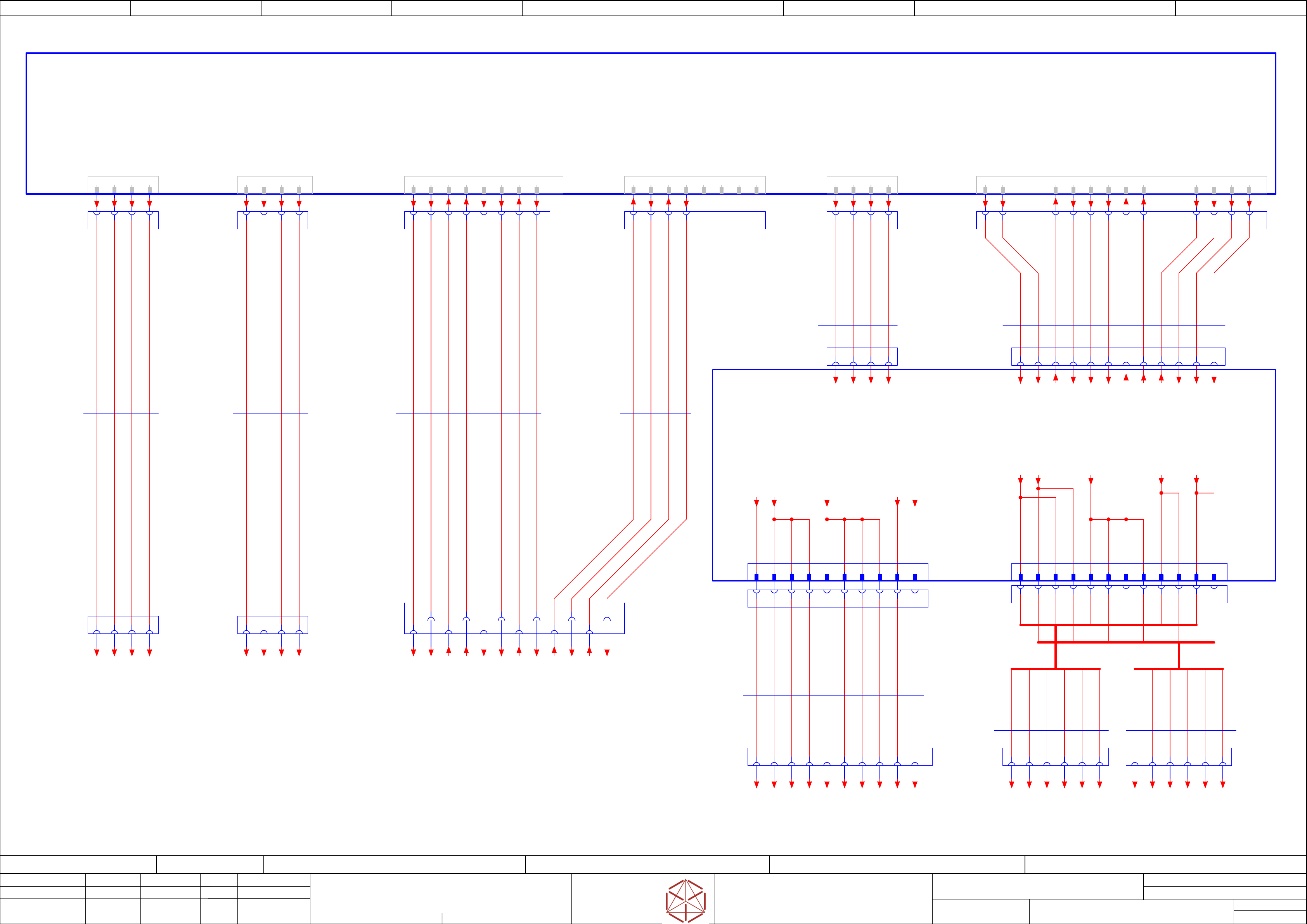
Cabling safety breaker to MGCU,
Cabling safety breaker to MGCU,
Cabling safety breaker to MGCU,
Cabling safety breaker to MGCU,
Distributor
Distributor
Distributor
Distributor
Replaced by
40
Weitergabe sowie Vervielfältigung dieser Unterlage, Verwertung und
Mitteilung des Inhalts nicht gestattet, soweit nicht ausdrücklich zugestanden.
Proprietary Data, company confidential.
All rights reserved
Copying of this document, giving it to others and the use or
communication of the contents thereof, are forbidden without express authority.
Doc. No.
00 01 02 03 04 05 06 07 08 09
Privileged business information.
Do not release
Offenders are liable to payment of damages. All rights are reserved in the
event of the grant or the registration of a utility model or design.
Zuwiederhandlungen verpflichten zu Schadenersatz. Alle Rechte vorbehalten,
insbesondere für den Fall der Patenterteilung oder GM-Eintragung vorbehalten.
Page:
Function: Power Supply TX, switched mode
==PS005=TX+ELS/40
drawing number:
03119265-030101LE3
Power_supply electric_slide_in
P
ower_supply electric_sl
ide_in
P
ower_supply electric_sl
ide_in
P
ower_supply electric_slide_in
GmbH & Co KG
ASM
Assembly Systems
Copyright reserved
Ed.
Original
Pingist
Date
Date
Modification
Appr
01.12.2016
Name
Version: Series from
V
ersion: S
eries f
r
om
V
ersion: Series from
Version: Series from
2016/Q4 TA500
2016/Q4 TA500
2016/Q4 TA500
2016/Q4 TA500
starting MC-Nr
.: TA500 2016/Q4 G. Pingist
1 2 3 4
-X21.CSB
-X21.CSB
-X21.CSB
-X21.CSB
1 2 3 4
[Power DC 300 V]
-X2p.MGCU2
-
X2p.MGCU2
-X2p.MGCU2
-
X2p.MGCU2
1 2 3 4
[Power DC 300 V]
-X2p.MGCU1
-
X2p.MGCU1
-X2p.MGCU1
-
X2p.MGCU1
1 2 3 4
-X22B.CSB
-X22B.CSB
-X22B.CSB
-
X22B.CSB
A1 A6
A1 A5
A3 A4 A5
A2 A3 A4 B1 B5B2 B3 B4 B6
B1 B6B2 B3 B4 B5
A2
A6
1 2 3 4 5 6 1 2 3 4 5 6
1 2 3 4
2-917542-2
300V Power
300V Power
300V Power
300V Power
-X21
-
X21
-X21
-X21
-A2
-
A2
-
A2
-
A2
Saf
et
y breaker unit
Safety breaker uni
t
Safety breaker unit
Safety breaker unit
PCB Pre-/discharge assembly
PCB Pr
e-/discharge assembly
PCB Pre-/discharge assembly
PCB Pr
e-/discharge assembly
03108631
2-917542-2
300V Power
300V Power
300V Power
300V Power
-X22B
-
X22B
-X22B
-X22B
1 2 3 4 A5B1A3B5
1318126-1
Safety Loop
Safety Loop
Safety Loop
Saf
ety Loop
& Signals
& Signals
& Signals
& Signals
-X29
-X29
-X29
-X29
A6B6 A2A1
1380 mm
4xAWG14
Single core
03112101
03112101
03112101
03112101 -02
-02
-02
-02
-W12
-
W12
-
W12
-
W12
RD AWG14
WH AWG14
1 2 3 4
1380 mm
4xAWG14
Single core
03112201
03112201
03112201
03112201 -02
-02
-02
-02
-W13
-
W13
-
W13
-
W13
1 2 3 4
1 2 3 4
1 2 3 4
Machine cable harness
to Distributor
Safety-loop
& Signals
-X22.DI
-X22.DI
-X22.DI
-X22.DI
570 mm
6x0,61
Single core UL/cUL Style
03112103
03112103
03112103
03112103 -02
-02
-02
-02
-W11.1
-
W11.1
-
W11.1
-
W11.1
B1 B2
A1 A2
-X30.CSB
-X30.CSB
-X30.CSB
-X30.CSB
Safet
y
Loop Extern
1 2 3 4 5
-X29.CSB
-X29.CSB
-X29.CSB
-X29.CSB
Safet
y Loop
& Signals
extern
B5 B6 A3 B1 A5 A1 A6 A2
620 mm
4x0,61
Single core UL/cUL Style
03112103
03112103
03112103
03112103 -02
-02
-02
-02
-W11.2
-
W11.2
-
W11.2
-
W11.2
6 7 8
1 2 3 4 5 6 7 8
-X30
-X30
-X30
-X30
Safet
y
Loop extern
Star Voltage
-X24A.FD
-X24A.FD
-X24A.FD
-X24A.FD
1 2 3 4
Control
-X24B.FD
-X24B.FD
-X24B.FD
-
X24B.FD
1 2 3 4 5 6 7 8 9 10 11 12
230 mm
4xAWG16
Single-wire
03116435
03116435
03116435
03116435 -02
-02
-02
-02
-W9
-
W9
-W9
-W9
330 mm
7x4xAWG16/3xAWG18/5xAWG20
Single-wire
03116436
03116436
03116436
03116436 -02
-02
-02
-02
-W10
-
W10
-W10
-W10
VT AWG16
BN AWG18
WH AWG18
WH AWG16
-X24A.CSB
-X24A.CSB
-X24A.CSB
-X24A.CSB
Star Voltage
1 2 3 4
-X24B.CSB
-X24B.CSB
-X24B.CSB
-
X24B.CSB
Safety control
signals to FDB
DC42V IN/OUT
1 2 8 9 13 1475 6 10 15 16
GY AWG16
1 32 4
-X24A
-X24A
-X24A
-X24A
Safet
y
switched 160V
21
-X24B
-X24B
-X24B
-X24B
Safet
y
control signals
42V IN/OUT
3 4 11 12
65 7 8 13 1514 169 10 11 123 4
RD AWG14
WH AWG14
RD AWG14
WH AWG14
RD AWG14
WH AWG14
A3
B3
A4
B4
A5
B5
A6
B6
PK AWG20
-X10
-X10
-X10
-X10
Distributor Power DC 24 V
D-3000 1-178318-2
7
GND24
8
GND24
9
PE
10
DC24V-PC2(F6)
1
DC24V(F3)
2
DC24V(F4)
3
DC24V(F4)
4
DC24V(F4)
5
GND24
6
GND24
-X21.DI
-X21.DI
-X21.DI
-X21.DI
Distributor
Power DC 24 V
2 41 3 6 85 7 109
-X10.FD
-X10.FD
-X10.FD
-X10.FD
1 2 3 4 5 6 7 8 9 10
300 mm
10xAWG20
Single-wire
03112133
03112133
03112133
03112133 -02
-02
-02
-02
-W27
-W27
-W27
-W27
BN AWG20
WH AWG20
GNYE AWG20
D-3000 178326-2
GCU1&2 supply
GCU1&2 supply
GCU1&2 supply
GCU1&2 supply
-X13
-X13
-X13
-X13
B1
P 24 V GCU 2 (F2)
B2
P 24 V GCU 2 (F2)
B3
GND24
B5
PowerEnable (F10)
B6
POWERFAIL (F10)
A1
P 24 V GCU 1 (F1)
A2
P 24 V GCU 1 (F1)
A3
GND24
A4
GND24
A5
PowerEnable (F10)
A6
POWERFAIL (F10)
B4
GND24
-X13.FD
-X13.FD
-X13.FD
-X13.FD
A1
A2
A3
A4
A5
A6
B1
B2
B3
B4
B5
B6
-X1p.MGCU1
-X1p.MGCU1
-X1p.MGCU1
-
X1p.MGCU1
-X1p.MGCU2
-X1p.MGCU2
-X1p.MGCU2
-
X1p.MGCU2
1500 mm
6xAWG20
Single core
03112112
03112112
03112112
03112112 -02
-02
-02
-02
-W21.1
-
W21.1
-
W21.1
-
W21.1
1590 mm
6xAWG20
Single core
03112112
03112112
03112112
03112112 -02
-02
-02
-02
-W21.2
-
W21.2
-
W21.2
-
W21.2
1 2 3 4 5 6 1 2 3 4 5 6
BN AWG20
WH AWG20
YE AWG20
WH AWG20
YE AWG20
WH AWG20
YE AWG20
WH AWG20
YE AWG20
BN AWG20
BN AWG20
-FD.A1
-FD.A1
-FD.A1
-FD.A1
Fuse- and Distribustion PCB
Fuse- and Distribustion PCB
Fuse- and Distribustion PCB
Fuse- and Distribustion PCB
03114948
BN AWG20
BN AWG20
BN AWG20
BN AWG20
BN AWG20
WH AWG20
WH AWG20
WH AWG20
GY AWG16
YE AWG20
YE AWG20
GY AWG16
GY AWG16
YE AWG20
YE AWG20
YE AWG20
BN AWG18
VT AWG16
WH AWG16
YE AWG20
YE AWG20
YE AWG20
YE AWG20
YE AWG20
PK AWG20
YE AWG20
YE AWG20
YE AWG20
YE AWG20
YE AWG20
-P-GND-21-1
==CSB+/42.01
-P-GND-21-2
==CSB+/42.02
-DC300V-21-1
==CSB+/42.01
-DC300V-21-2
==CSB+/42.01
-P-GND-22b-1
==CSB+/42.04
-P-GND-22b-2
==CSB+/42.04
-DC300V-22b-1
==CSB+/42.03
-DC300V-22b-2
==CSB+/42.03
-Loop2_Begin
==CSB+/41.03
-DC24V_S_DIS
==CSB+/42.08
-DI13_PWR_enabled
==CSB+/42.08
-Loop2-End
==CSB+/41.04
-DI0_Safety_Loop_OK
==CSB+/41.03
-Safety_Start_SSK
==CSB+/41.03
-Loop1_Begin
==CSB+/41.03
-Loop1-End
==CSB+/41.04
-Safety_Loop1_ext.in
==CSB+/41.00
-Safety_Loop1_ext.out
==CSB+/41.00
-Safety_Loop2_ext.in
==CSB+/41.00
-Safety_Loop2_ext.out
==CSB+/41.01
-DC42V-S-1
==CSB+/42.05
-DC24V-S
==CSB+/42.07
-POWER_ENABLE
==CSB+/42.06
-DC42V-S-2
==CSB+/42.06
-24V-in-F12
==CSB+/42.07
-24V-In-F11
DC 24 V Safety supply
==CSB+/41.02
-GND_1
==CSB+/41.02
-DC160V-S-1
==CSB+/42.04
-DC160V-S-2
==CSB+/42.05
-P-GND-24-2
==CSB+/42.05
-P-GND-24-4
==CSB+/42.05
-CH1-OK
==CSB+/41.01
-CH2-OK
==CSB+/41.02
-42V1_F16
DC 42 V power supply
==CSB+/42.06
-42V2_F16
DC 42 V power supply
==CSB+/42.06
-PCC-POWER-OK
==CSB+/41.02
-POWER_ENA_FD
/39.08
-24V-In-F11
/39.08
-GND_1
/39.08
-DC160V-S-1
/39.07
-DC160V-S-2
/39.07
-P-GND-24-2
/39.07
-P-GND-24-4
/39.07
-PCC-POWER-OK
/39.08
-DC24V-S
/39.09
-24V-in-F12
/39.09
-CH1-OK
/39.09
-CH2-OK
/39.09
-24V-F3
/39.02
-24V-F1
/39.02
-24V-F2
/39.02
-24V-F4
/39.02
-GND24
/39.02
-GND24
/39.02
-24V-F6
/39.03
-PE_CON
/39.04
-PWR-ENABLE
/39.08
-PWR-FAIL
/39.02
-DC24V_S_DIS
==DI+/43.03
-Safety_Start_SSK
==DI+/43.03
-Loop1_OUT
==DI+/43.02
-Loop2_OUT
==DI+/43.02
-Loop1_IN
==DI+/43.02
-Loop2_IN
==DI+/43.03
-Safety_Loop1_ext.in
==DI+/43.03
-Safety_Loop1_ext.out
==DI+/43.03
-Safety_Loop2_ext.in
==DI+/43.04
-Safety_Loop2_ext.out
==DI+/43.04
-DI13_PWR_enabled
==DI+/43.03
-DI0_Safety_Loop_OK
==DI+/43.03
-GND_6
==DI+/43.06
-GND_5
==DI+/43.06
-24V_1(F3)
==DI+/43.05
-PE1
==DI+/43.06
-GND_7
==DI+/43.06
-24V_2(F4)
==DI+/43.05
-24V_3(F4)
==DI+/43.06
-24V_4(F4)
==DI+/43.06
-GND_8
==DI+/43.06
-24V_PC2(F6)
==DI+/43.07
-DC300V_1
==CH+GA/55.02
-DC300V_2
==CH+GA/55.02
-P_GND_1
==CH+GA/55.02
-P_GND_2
==CH+GA/55.02
-DC300V_1
==CH+GA/57.02
-DC300V_2
==CH+GA/57.02
-P_GND_1
==CH+GA/57.02
-P_GND_2
==CH+GA/57.02
-24V(F2)_1
==CH+GA/57.00
-GND24_1
==CH+GA/57.00
-24V(F2)_2
==CH+GA/57.00
-GND24_2
==CH+GA/57.01
-PWR_FAIL
==CH+GA/57.01
-PWR_ENABLE
==CH+GA/57.01
-24V(F1)_1
==CH+GA/55.00
-GND24_1
==CH+GA/55.00
-24V(F1)_2
==CH+GA/55.00
-GND24_2
==CH+GA/55.01
-PWR_FAIL
==CH+GA/55.01
-PWR_ENABLE
==CH+GA/55.01
-42V1_F16
/39.09
-42V2_F16
/39.09
-DC42V-S-1
/39.08
-DC42V-S-2
/39.08