Detailed Circuit Diagrams Folder.pdf - 第48页
Sheet Size DIN A2 electric_schematic_TX electric_schematic_TX electric_schematic_TX electric_schematic_TX 90012154-010301LE3 Replaced by Contactor based safety br eaker: power Contactor based safety br eaker: power Conta…
Sheet
Size DIN A2
electric_schematic_TX
electric_schematic_TX
electric_schematic_TX
electric_schematic_TX
90012154-010301LE3
Replaced by
Contactor based safety breaker: logic
Contactor based safety breaker: logic
Contactor based safety breaker: logic
Contactor based safety breaker: logic
Replaced by
41
Weitergabe sowie Vervielfältigung dieser Unterlage, Verwertung und
Mitteilung des Inhalts nicht gestattet, soweit nicht ausdrücklich zugestanden.
Proprietary Data, company confidential.
All rights reserved
Copying of this document, giving it to others and the use or
communication of the contents thereof, are forbidden without express authority.
Doc. No.
0 1 2 3 4 5 6 7 8 9
Privileged business information.
Do not release
Offenders are liable to payment of damages. All rights are reserved in the
event of the grant or the registration of a utility model or design.
Zuwiederhandlungen verpflichten zu Schadenersatz. Alle Rechte vorbehalten,
insbesondere für den Fall der Patenterteilung oder GM-Eintragung vorbehalten.
Page:
Function: Contactor Safety Breaker
==CSB=TX/41
drawing number:
03112066-020101LE3
Contactor Safety Breaker
Contactor Saf
et
y B
r
eak
er
Contactor Safety Breaker
Contactor Safety Breaker
GmbH & Co KG
ASM
Assembly Systems
Copyright reserved
Ed.
Original
Pingist
Date
Schnedlitz W.
Date
Modification
Appr
01.12.2016
Name
Version: Series from
V
ersion: S
eries f
r
om
V
ersion: Series from
Version: Series from
2016/Q4 TA500
2016/Q4 TA500
2016/Q4 TA500
2016/Q4 TA500
starting MC-Nr
.: TA500 2016/Q4 G. Pingist
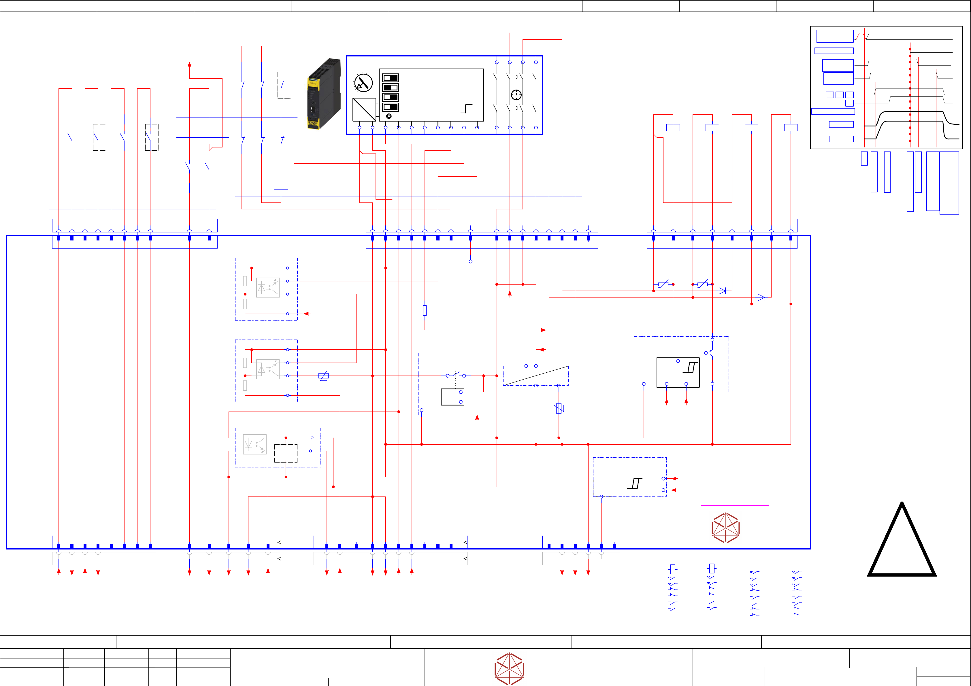
LOGIC
=~
=
+ -
+ -
+ -
+ -
1 | Autostart/Monitored Start
1 | Autostart/Monitored Start
1 | Autostart/Monitored Start
1 | Autostart/Monitored Start
2 | Cross Fault Detection Off/On
2 | Cross Fault Detection Off/On
2 | Cr
oss Fault Detection Off/On
2 | Cross Fault Detection Off/On
3 | 2 single ch. sensors / 1 double channel Sensor
3 | 2 single ch. sensors / 1 double channel Sensor
3 | 2 single ch. sensors / 1 double channel Sensor
3 | 2 single ch. sensors / 1 double channel Sensor
4 | Startup Test Yes/No
4 | Startup T
est Y
es/No
4 | Startup T
est Y
es/No
4 | Startup T
est Yes/No
SET / RESET
SET / RESET
SET / RESET
SET / RESET
T
T
T
T
- not used -
Set delay time
Set delay time
Set delay time
S
et delay time
to 140 ms +/- 40 ms
to 140 ms +/- 40 ms
to 140 ms +/- 40 ms
to 140 ms +/- 40 ms
0,05
0,5
1
2
2,5
3s
S
S
S
S
Timing chart
Timing chart
Timing chart
Timing chart
Start
Start
Start
Start
Precharge done
Precharge done
Precharge done
Precharge done
Emergency STOP event
Emergency STOP event
Emergency STOP event
Emergency STOP event
K1,K2, K3, K4 off delay;
K1,K2, K3, K4 off delay;
K1,K2, K3, K4 off delay;
K1,K2, K3, K4 off delay;
Discharge external Cap
Discharge external Cap
Discharge external Cap
Discharge external Cap
-->Power of
f
-->Power off
-->Power off
-->P
ower off
Safety relais off
Safety relais off
Safety relais off
Safety relais off
Safety relaais off delay
Safety relaais off delay
Safety relaais off delay
Safety relaais off delay
> 100 ms; <180 ms
> 100 ms; <180 ms
> 100 ms; <180 ms
> 100 ms; <180 ms
Precharge start
Precharge start
Precharge start
Precharge start
DC 300 V
DC 300 V
DC 300 V
DC 300 V
DC 160 V
DC 160 V
DC 160 V
DC 160 V
K2
K2
K2
K2
POWER_ENABLE
POWER_ENABLE
POWER_ENABLE
POWER_ENABLE
K1
K1
K1
K1 K4
K4
K4
K4K3
K3
K3
K3
PCC output
PCC output
PCC output
PCC output
delayed
delayed
delayed
dela
yed
PCC output
PCC output
PCC output
PCC output
not delayed
not delayed
not delayed
not dela
yed
EMG_Loop_OK
EMG_Loop_OK
EMG_Loop_OK
EMG_Loop_OK
SW_CTRL_ON
SW_CTRL_ON
SW_CTRL_ON
SW_CTRL_ON
Start
Start
Start
Start
Changes:
Changes:
Changes:
Changes:
Use Standard NC contact at aux block at K3 for discharge
Use Standard NC contact at aux block at K3 for discharge
Use Standard NC contact at aux block at K3 for discharge
Use Standard NC contact at aux block at K3 for discharge
User NC contact at contactor K4 for discharge
User NC contact at contactor K4 for discharge
User NC contact at contactor K4 for discharge
User NC contact at contactor K4 for discharge
Remarks
1. DIAG_K_N is blocking START signal
if pre- or discharge resistor monitoring
signals error (overheating or disconnection)
2. DIAG_K_RD is disconnecting 24V supply
of safety relais if discharge monitoring
reports discharge error.
3. Safety relais supply voltage is disconnected
if there is undervoltage in unit suply voltage.
Supply voltage can be monitored at output
PCC-POWER-OK
4. Set safety relais (K5) to dalay time between
140 ms and 200 ms.
Delay time shorter will cause MGCU error
'Link voltage supply error' due to voltage
increase while drives breaking phase.
Delay time longer will cause increase in
danger to operator if cover is opened.
5. In General:
Press STOP button first prior to open cover.
STOP button will not trigger safety breaker but
will stop motion avoiding both danger to motion
and malfunction of MGCU DC link supply.
6. Make sure to connect T1 of PCB to main
grounding terminal. If this connection is missing
there will be no discharge functionality and
Safety breaker unit will not activate output
voltages!
Safety component!
Saf
ety component!
Safety component!
Saf
ety component!
Use specified parts only!
Use speci
fied parts only!
Use specified parts only!
Use specified parts only!
24V0 Safety_unit supply
24V0 Safety_unit supply
24V0 Safet
y_unit supply
24V0 Safety_unit supply
ITS4141
Load-switch
03108631-010301LE3
ITS4141
Load-switch
&
GND_Safety
GND_Safety
GND_Safety
GND_Saf
ety
24V_PCC
24V_PCC
24V_PCC
24V_PCC
&
-F2
-F1
&
A1
INK
IN1
IN2
A2
13
23
37
47
INF
INS
38
48
T2
T1
PAR
-K5
-K5
-K5
-K5
Safety relay 2-chanel
Saf
ety relay 2-chanel
Saf
ety relay 2-chanel
Safety relay 2-chanel
24V AC
03114826-
Siemens
Siemens
Siemens
Siemens
3SK1121-xCB41
14
24
Safety Relais connect
-X100.CSB
-X100.CSB
-X100.CSB
-X100.CSB
1 2 3 4 5 6 7 8
nc
9 10 11
nc
12 13 14 15 16
nc
-K1
-K1
-K1
-K1
Relay Safety
300V, 160V
A1
A2
A1 A2
2 1
/42.3
4 3
/42.4
2122
.2
3231
.2
1413
4443
.1
SIE.3TC4417-0AB4
-K3
-K3
-K3
-K3
Relay Safety
42V, 24V
A1
A2
1 2
/42.9
3 4
/42.8
6 5
/42.9
2221
/42.2
5453
.1
6463
.0
7271
8281
.2
EAT.DILA32-XHIR22
EAT.DILM17-01(RDC24)
-K4
-K4
-K4
-K4
Relay
Pre-charge
300V, 160V
A1
A2
1 2
/42.1
3 4
5 6
/42.2
2221
.2
5453
.1
6463
.1
7271
/42.1
8281
EAT.DILA32-XHIR22
EAT.DILM17-01(RDC24)
1
2 4
2 81 2 3 4 5 6 7 8 9 10 65 7
-X28.CSB
-X28.CSB
-X28.CSB
-X28.CSB
AuxContacts
-X27.CSB
-X27.CSB
-X27.CSB
-
X27.CSB
Safety
contactor
-X31.CSB
-X31.CSB
-X31.CSB
-X31.CSB
Safet
y-controlled
DC 24V
-K2
-K2
-K2
-K2
Relay Safety
300V, 160V;
Power enable
A1
A2
A1 A2
2 1
/42.3
4 3
/42.4
2221
.2
3132
.2
1413
/42.8
4443
.2
SIE.3TC4417-0AB4
3
4
3
-K1
-K1
-K1
-K1
43
44
1 5 6
-K4
-K4
-K4
-K4
21
22
-K1
-K1
-K1
-K1
22
21
-K1
-K1
-K1
-K1
31
32
-K2
-K2
-K2
-K2
21
22
-K2
-K2
-K2
-K2
32
31
-K2
-K2
-K2
-K2
43
44
5
Auxiliary contacts
10x0,5
SIngle core
#03119736-W5
YE
YE
YE
YE
YE
YE
YE
YE
Cable safety relais
14x0,5
Single core
#03119737-W6
PK
PK
PK
YE
BN
WH
YE
YE
YE
BN
YE
BN
BN
Cable Contactor Control
450/750V
7x0,5
Single core MULTI-STANDARD SC 2.1
#03119735-W4
PK
PK
PK
PK
WH
WH
WH
WH
YE
YE
BN
Single wire connections
#03121398-W7.1
6x0,5
0,5 BN
0,5 YE
0,5 YE
0,5 YE
0,5 YE
Single wire connections
1x0,5
#03121398-W7.2
0,5 YE
A5
B181615 5 B5
-X24B.CSB
-X24B.CSB
-X24B.CSB
-X24B.CSB
Safety control
signals to FDB
-X29.CSB
-X29.CSB
-X29.CSB
-X29.CSB
Safety Loop
& Signals
extern
A67 B2 B3 B4A4 B6 A31 2 3 4 5 6 7 8
-X30.CSB
-X30.CSB
-X30.CSB
-X30.CSB
Safet
y
Loop Extern
0,5 BN
YE
Single wire connections
1x0,5
Single core
#03121398-W7.4
Cable Low Voltage Control
#03119733-W2.3
2x0,5
OUT2_ND
DC 24V Safety controlled PL=d
3
GND Safety
8
EMG_Loop_OK
A5
Loop2-IN
B1
nc
B2
Loop1_IN
A3
1 2 3 4 5 6 7 8
15
OUT2_ND
9
24V0
10
24Vext
11
24V0
12
24V0
13
OUT2_D
16
OUT1_ND (nc)
1
K1-A1
GND Safety
2
GND Safety
4
2
GND
8
GND
1 2 3 4 5 6 7 8 9 10
CH2-OK
16
CH1-OK
15
14
OUT1_D
6
GND
24V-PCC
B5
24V-PCC
B6
5
A3-K1
7
K4-A1
nc
1
PPWR-present
5
nc
6
-A2
-A2
-A2
-A2
Safet
y breaker unit
Safety breaker uni
t
Safety breaker unit
Safety breaker unit
PCB Pre-/discharge assembly
PCB Pr
e-/discharge assembly
PCB Pre-/discharge assembly
PCB Pr
e-/discharge assembly
-X28
-X28
-X28
-X28
AuxContacts in
-X100
-X100
-X100
-X100
Safet
y relais connect
-X27
-X27
-X27
-X27
Safet
y
contactor
-X30
-X30
-X30
-X30
Safet
y
Loop extern
-X24B
-X24B
-X24B
-X24B
Safety
control signals
-X29
-X29
-X29
-X29
Safet
y Loop
& Signals
-X31
-X31
-X31
-X31
Auxi
liary
(RFU signals)
3
K2-A1
4
GND/K5
START_SIG
Safety Start
Signal input
A6
-Out
-PPWR.PRESENT
-PPWR.PRESENT
-PPWR.PRESENT
-PPWR.PRESENT
Voltage-Trigger
300V/160V PPWR-present
(300V > 60V && 160V > 60V)
P300V
P160V
-K2
-K2
-K2
-K2 Start B
-
+
+
in
out
1
Supply
2
GND
3
Loop1_IN
4
Loop2_IN
5
T2
6
START
7
TestLoopIn
8
nc
GND
DIAGN_K_N
-K3
-K3
-K3
-K3 Start A
-
+
+
in
out
GND
START_SIG
24V0
Safety unit
5
+
+
-
-K1
-K1
-K1
-K1
Safety loop
closed signal
24V0
L_CLSD
24V_PCC
7
nc
A4
nc
B3
nc
B4
-R42
60VAC(100mW)
-R43
60VAC(100mW)
-D18
-D50
-R128
0R
Test_loop_IN
-P300.pbc
-P300.pbc
-P300.pbc
-P300.pbc
Voltage-Trigger
300V precharge bypass control
Out
GND
Supply
24V.Safe
24V.Safe
24V.Safe
24V.Safe
Safe DC
internal supply
24VSafe
24V0
24V_PCC
24V_PCC
24V_PCC
24V_PCC
PCC supply
undervoltage lockout
OUT
24V_PCC
IN
24V0
DIAG
U_Mon
-K4
-K4
-K4
-K4
53
54
-K4
-K4
-K4
-K4
63
64
-K3
-K3
-K3
-K3
53
54
-K3
-K3
-K3
-K3
63
64
-K3
-K3
-K3
-K3
81
82
==+-GND_2
==+-GND_3
==+-24V_F12_Aux
/42.7
==+-24V_safety
not connected
-DI0_Safety_Loop_OK
==PS005+ELS/40.3
-24V-In-F11
==PS005+ELS/40.8
-GND_1
==PS005+ELS/40.8
-Loop2-End
==PS005+ELS/40.3
-CH1-OK
==PS005+ELS/40.9
-CH2-OK
==PS005+ELS/40.9
-Loop1_Begin
==PS005+ELS/40.3
-Safety_Start_SSK
==PS005+ELS/40.3
-PCC-POWER-OK
==PS005+ELS/40.8
-Loop2_Begin
==PS005+ELS/40.3
-Loop1-End
==PS005+ELS/40.3
-Safety_Loop1_ext.in
==PS005+ELS/40.4
-Safety_Loop1_ext.out
==PS005+ELS/40.4
-Safety_Loop2_ext.in
==PS005+ELS/40.5
-Safety_Loop2_ext.out
==PS005+ELS/40.5
-P300V
/42.1
-P160V
/42.4
==+-DIAGN_K_N
24V-Supply
/42.7
DC 24 V power supply
to external signals
VDIFFMON1
300V
/42.2
VDIFFMON2
160V
/42.2
24VSafe
Safe supply
/42.6
P_GND
Power Ground
/42.6
DIAGN_RD_N
/42.5
Sheet
Size DIN A2
electric_schematic_TX
electric_schematic_TX
electric_schematic_TX
electric_schematic_TX
90012154-010301LE3
Replaced by
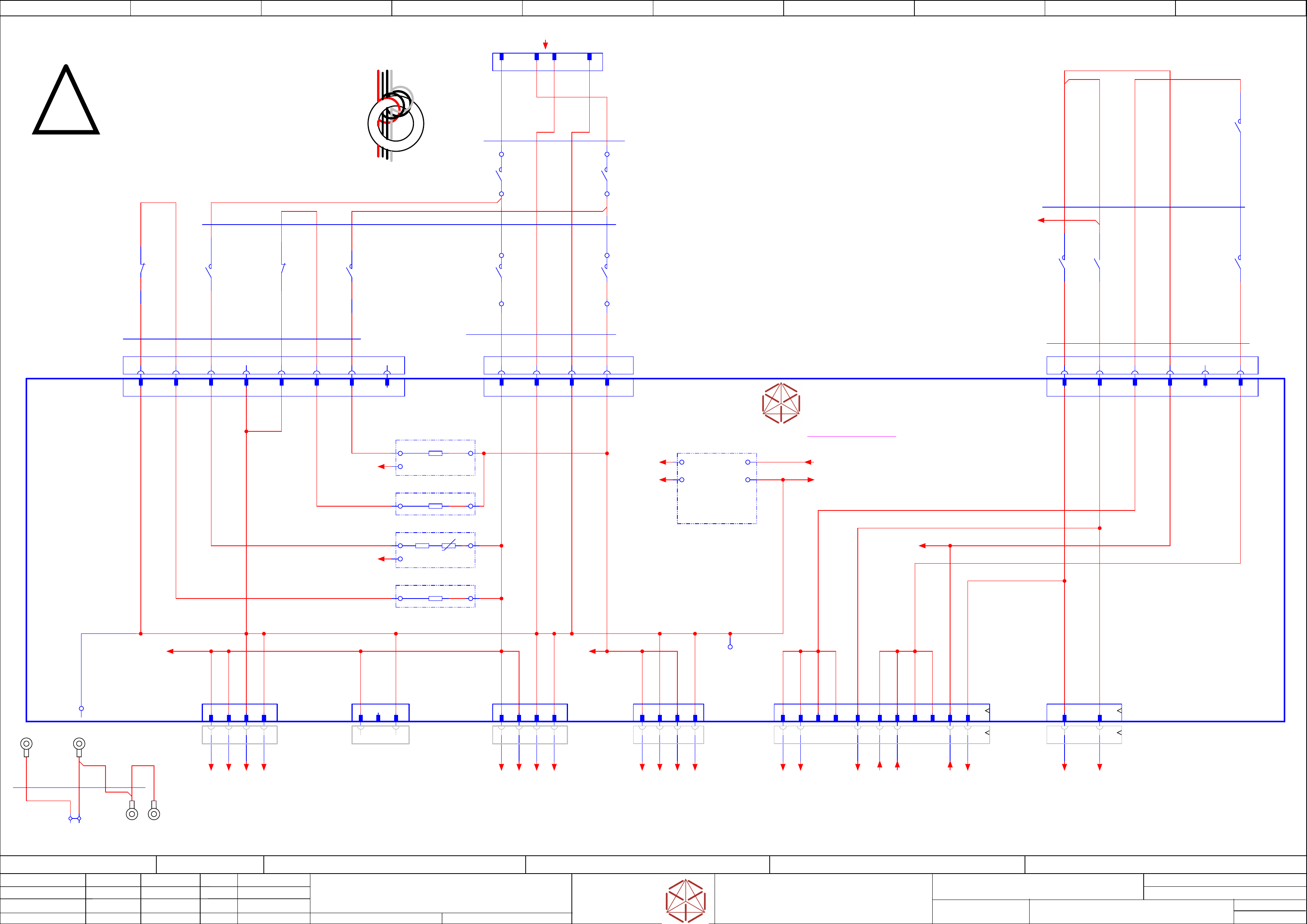
Contactor based safety breaker: power
Contactor based safety breaker: power
Contactor based safety breaker: power
Contactor based safety breaker: power
Replaced by
42
Weitergabe sowie Vervielfältigung dieser Unterlage, Verwertung und
Mitteilung des Inhalts nicht gestattet, soweit nicht ausdrücklich zugestanden.
Proprietary Data, company confidential.
All rights reserved
Copying of this document, giving it to others and the use or
communication of the contents thereof, are forbidden without express authority.
Doc. No.
0 1 2 3 4 5 6 7 8 9
Privileged business information.
Do not release
Offenders are liable to payment of damages. All rights are reserved in the
event of the grant or the registration of a utility model or design.
Zuwiederhandlungen verpflichten zu Schadenersatz. Alle Rechte vorbehalten,
insbesondere für den Fall der Patenterteilung oder GM-Eintragung vorbehalten.
Page:
Function: Contactor Safety Breaker
==CSB=TX/42
drawing number:
03112066-020101LE3
Contactor Safety Breaker
Contactor Saf
et
y B
r
eak
er
Contactor Safety Breaker
Contactor Safety Breaker
GmbH & Co KG
ASM
Assembly Systems
Copyright reserved
Ed.
Original
Pingist
Date
Schnedlitz W.
Date
Modification
Appr
01.12.2016
Name
Version: Series from
V
ersion: S
eries f
r
om
V
ersion: Series from
Version: Series from
2016/Q4 TA500
2016/Q4 TA500
2016/Q4 TA500
2016/Q4 TA500
starting MC-Nr
.: TA500 2016/Q4 G. Pingist
apply 1 winding
near X19.CSB
use all wires
- not used -
S
S
S
S
-X1
Cable lug
crimp 2.5 mm²
M5
-X3
Cable lug
crimp 2.5 mm²
M5
-X2
Cable lug
crimp 2.5 mm²
M5
-X4
Cable lug
crimp 2.5 mm²
M5
Safety component!
Safety component!
Safety component!
Saf
ety component!
Use specified parts only!
Use speci
fied parts only!
Use specified parts only!
Use specified parts only!
300V
300V
300V
300V
PGND
PGND
PGND
PGND
03108631-010301le3
A1 A2 B1 B2
-X20.CSB
-X20.CSB
-X20.CSB
-X20.CSB
Power
-in
300V, 160V
B3B1 B2
-X25.CSB
-X25.CSB
-X25.CSB
-X25.CSB
Low vol
tage control
A1 A2 A3
-K1
-K1
-K1
-K1
Switch
160V
4
3
-K1
-K1
-K1
-K1
Switch
300V
2
1
-K2
-K2
-K2
-K2
Switch
300V
2
1
-K2
-K2
-K2
-K2
Switch
160V
4
3
-K3
-K3
-K3
-K3
Switch
24V
3
4
-K3
-K3
-K3
-K3
Switch
42V
1
2
-K3
-K3
-K3
-K3
Switch
42V
6
5
-K2
-K2
-K2
-K2
Switch
24V
13
14
-K4
-K4
-K4
-K4
Pre-
charge
160V
5
6
-K4
-K4
-K4
-K4
Pre-
charge
300V
1
2
B3B1 B2 B4
-X26.CSB
-X26.CSB
-X26.CSB
-X26.CSB
Pre/Dischar
ge control
K1, K2, K4
A1 A2 A3 A4
-X19.CSB
-X19.CSB
-X19.CSB
-X19.CSB
Power
-in
300V, 160V
B1
P-GND
A1
DC 300V in
B3
P-GND
A3
DC 160V in
Cable Pre/Discharge
6x1,5
500 mm
Single core
#03119734-W3
BK
BK
GY
RD
BK
BK
Cable Power input
4x2,5
390 mm
Single Core
#03119732-W1
WH
WH
RD
GY
4x2,5
Single Core
#03119732-W1
Cable Low Voltage Control
450/750V
5x
Single core MULTI-STANDARD SC 2.1
#03119733-W2.1
GY
BN
GY
YE
YE
GY
RD
Cable Low Voltage Control
450/750V
2x1,5
Single core MULTI-STANDARD SC 2.1
#03119733-W2.2
BN
A2
A1
-X21.CSB
-X21.CSB
-X21.CSB
-X21.CSB
300V Power
3 41 2
-X22.CSB
-X22.CSB
-X22.CSB
-X22.CSB
300V Power
-X22b.CSB
-X22b.CSB
-X22b.CSB
-
X22b.CSB
300V Power
-X29.CSB
-X29.CSB
-X29.CSB
-X29.CSB
Safet
y Loop
& Signals
extern
1 3 3 41 2
-X24B.CSB
-X24B.CSB
-X24B.CSB
-
X24B.CSB
Safety control
signals to FDB
DC42V IN/OUT
1 2 9 10 13 1463 4 11 122
-X24A.CSB
-X24A.CSB
-X24A.CSB
-X24A.CSB
Star Vol
tage
1 2 3 4
GY
Single wire connections
4x2,5
Single wire
#03121398-W7.3
GY
GY
RD
RD
-X300(PE)
-X300(PE)
-X300(PE)
-X300(PE)
stripping 5mm
1
Single connections CSB
Single Core
#03121398-W7.5
GNYE
GNYE
GNYE
-K3
-K3
-K3
-K3
DISCHARGE
CH2
21
22
P300V
1
P300V
2
PGND
3
PGND
4 104
DC 160V out
1
DC 160V out
3
GND Power
2
GND Power
4
B2
Power 160V
B1
Power GND
A2
Power GND
A1
Power300V
24V_SW
safety_controlled PL=c
A2
PWR_EN
Power enabled
A1
-X20
-X20
-X20
-X20
Power
-in
300V, 160V
921
B1
24V_Supply
B3
P42V_F16
B2
-X25
-X25
-X25
-X25
Low vol
tage control
A3
P42V_S
A2
PWR_EN
A1
24V_SW
-X21
-X21
-X21
-X21
300V Power
-X22
-X22
-X22
-X22
300V Power
-X22B
-X22B
-X22B
-X22B
300V Power
-X24A
-X24A
-X24A
-X24A
Safet
y
switched 160V
-X29
-X29
-X29
-X29
Safet
y Loop
& Signals
T1
PE
P300V
1
NC
2
PGND
3
P300V
1
P300V
2
PGND
3
PGND
4
-X24B
-X24B
-X24B
-X24B
Safet
y
control signals
42V IN/OUT
B1
P_GND
B3
160V_PRE
B2
DISCHARGE CONT2
B4
n/c
-X26
-X26
-X26
-X26
Pre/Dischar
ge control
A4
P_GND
A3
300V_PRE
A2
DISCHARGE CONT1
A1
P_GND
DC 42 V safety-
controlled
3
Power enabled
6 12
DC 42 V F16
11
24V_SW
14
24V Supppy
13
-T1:1
PGND
-DIAG
-DIAG
-DIAG
-DIAG
Precharge and discharge
resistor diagnostic
and error detection
Out11
Out22 Supply 3
GND 4
-Precharging.160V
-Precharging.160V
-Precharging.160V
-Pr
echarging.160V
-Precharging.300V
-Precharging.300V
-Precharging.300V
-Pr
echarging.300V
-Discharge.160V
-Discharge.160V
-Discharge.160V
-Discharge.160V
-R
-R
-R
-R_Th
Voltage monitor
Voltage monitor
-R
-Discharge.300V
-Discharge.300V
-Discharge.300V
-Discharge.300V
-A2
-A2
-A2
-A2
Safet
y breaker unit
Safety breaker uni
t
Safety breaker unit
Safety breaker unit
PCB Pre-/discharge assembly
PCB Pr
e-/discharge assembly
PCB Pre-/discharge assembly
PCB Pr
e-/discharge assembly
-K4
-K4
-K4
-K4
DISCHARGE
CH1
71
72
BK
==+-24V_F12_Aux
-K2:43 /41.1
-POWER_ENABLE
==PS005+ELS/40.8
-DC160V-S-1
==PS005+ELS/40.6
-P-GND-21-1
==PS005+ELS/40.1
-P-GND-21-2
==PS005+ELS/40.1
-DC300V-21-1
==PS005+ELS/40.0
-DC300V-21-2
==PS005+ELS/40.0
-P-GND-22b-1
==PS005+ELS/40.2
-P-GND-22b-2
==PS005+ELS/40.2
-DC300V-22b-1
==PS005+ELS/40.1
-DC300V-22b-2
==PS005+ELS/40.2
-DC160V-S-2
==PS005+ELS/40.6
-P-GND-24-2
==PS005+ELS/40.6
-P-GND-24-4
==PS005+ELS/40.6
-24V-in-F12
==PS005+ELS/40.9
-DC24V_S_DIS
==PS005+ELS/40.4
-DI13_PWR_enabled
==PS005+ELS/40.3
-42V1_F16
==PS005+ELS/40.8
-42V2_F16
==PS005+ELS/40.8
-DC42V-S-2
==PS005+ELS/40.7
-DC42V-S-1
==PS005+ELS/40.7
-DC24V-S
==PS005+ELS/40.9
24V-Supply
/41.5
-P300V
/41.6
-P160V
/41.6
DIAGN_RD_N
/41.4
DIAGN_K_N
==EMG=TX_EMG+CSB/141.3
24VSafe
/41.5
Safe supply
P_GND
/41.5
Power Ground
VDIFFMON1
/41.6
VDIFFMON2
/41.7
-PWR-160/300V
==PS005+ELS/38.1
Sheet
Size DIN A2
electric_schematic_TX
electric_schematic_TX
electric_schematic_TX
electric_schematic_TX
90012154-010301LE3
Replaced by
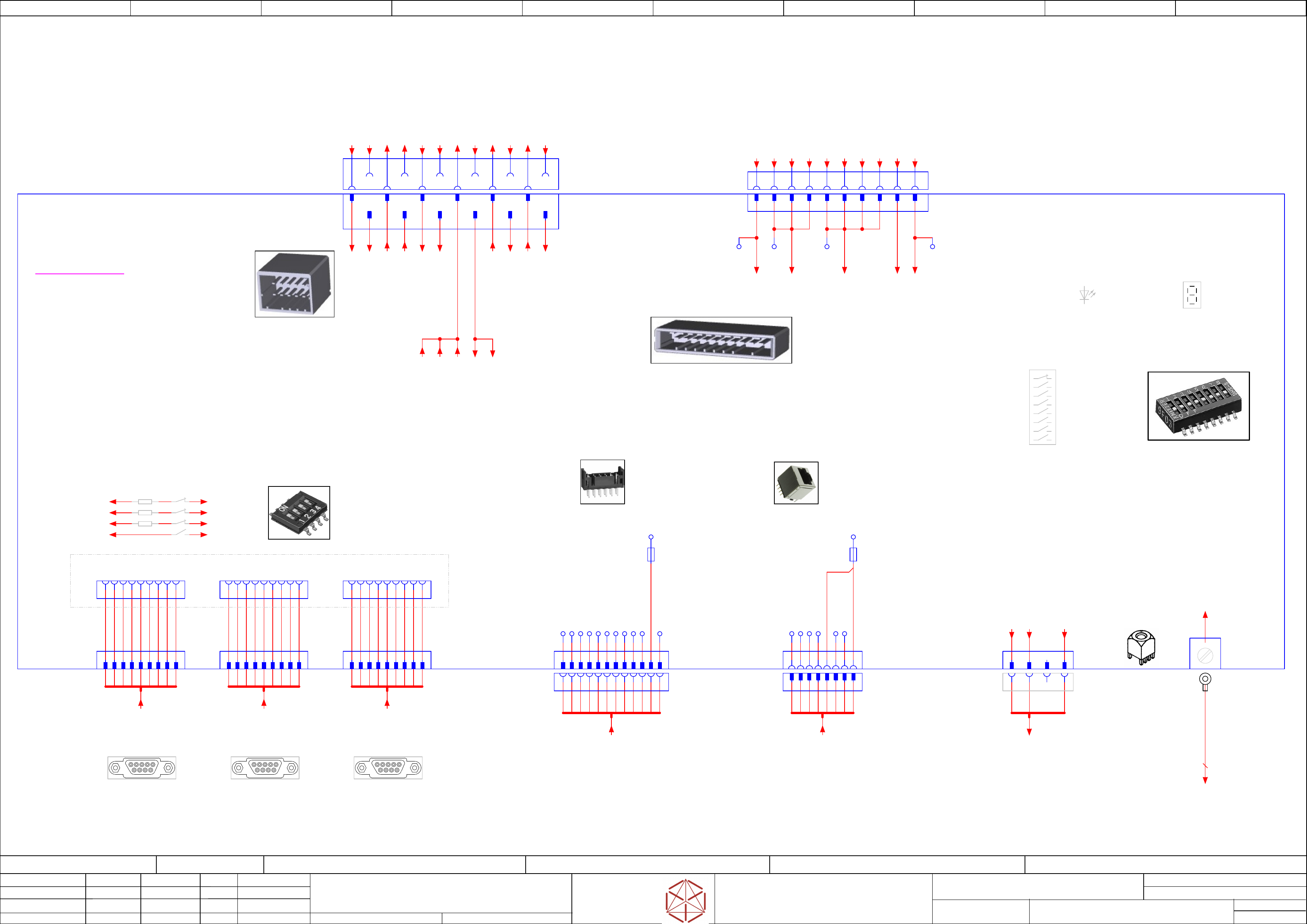
Distributor Connector -X21, -X22 /
Distributor Connector -X21, -X22 /
Distributor Connector -X21, -X22 /
Distributor Connector -X21, -X22 /
-X1, -X2, -X3 /
-X1, -X2, -X3 /
-X1, -
X2, -X3 /
-X1, -X2, -X3 /
- X11,-X14
- X11,-X14
- X11,-X14
- X11,-X14
Replaced b
y
43
Weitergabe sowie Vervielfältigung dieser Unterlage, Verwertung und
Mitteilung des Inhalts nicht gestattet, soweit nicht ausdrücklich zugestanden.
Proprietary Data, company confidential.
All rights reserved
Copying of this document, giving it to others and the use or
communication of the contents thereof, are forbidden without express authority.
Doc. No.
00 01 02 03 04 05 06 07 08 09
Privileged business information.
Do not release
Offenders are liable to payment of damages. All rights are reserved in the
event of the grant or the registration of a utility model or design.
Zuwiederhandlungen verpflichten zu Schadenersatz. Alle Rechte vorbehalten,
insbesondere für den Fall der Patenterteilung oder GM-Eintragung vorbehalten.
Page:
Function: Distributor
==DI=TX/43
drawing number:
03123463-020101LE3
Distributor
Distributor
Distributor
Distributor
GmbH & Co KG
ASM
Assembly Systems
Copyright reserved
Ed.
Original
Pingist
Date
Date
Modification
Appr
01.12.2016
Name
Version: Series from
V
ersion: S
eries f
r
om
V
ersion: Series from
Version: Series from
2016/Q4 TA500
2016/Q4 TA500
2016/Q4 TA500
2016/Q4 TA500
starting MC-Nr
.: TA500 2016/Q4 G. Pingist
-PE
Terminal
Ring Tongue M5
03121427-010201le3
-To Fuse and Distribution -
-To Fuse and Distribution -
-To Fuse and Distribution -
-
To Fuse and Distribution -
(extern Service) (PC 2)
-To Safety Breaker -
-
T
o Saf
et
y B
reaker -
-To Safety Breaker -
-To Safety Breaker -
MC-identifcation
reserved
reserved
reserved
reserved
Serial-bootstrap
CAN-bootstrap
Reset-state
Option Switches
Dip-Switch SW1
LED-DISPLAY
LED-DISPLAY
LED-DISPLAY
LED-DISPL
AY
- GREEN -
- GREEN -
- GREEN -
- GREEN -
-LED1
-LED1
-LED1
-LED1
Display
Reset-LED
Reset-LED
Reset-LED
R
eset-LED
- RED -
- RED -
- RED -
- RED -
-D66
-D66
-D66
-D66
Reset
-X14
-X14
-X14
-X14
RS485
RS485
RS485
RS485
for PSU
f
or PSU
f
or PSU
for PSU
1 2 3 4 5 6 87
-X14.DI
-X14.DI
-X14.DI
-
X14.DI
RS485/PSU
RJ45
1 2 3 4 5 6 7 8
1 2 3 4 6 7 85
LITTLEFUSE
33V 1,1A
SMT 1812
1 2 3 4 6 7 8 95 1 2 3 4 6 7 8 95 1 2 3 4 6 7 8 95
CAN Service-Connection (Sub-D)
CAN Service-Connection (Sub-D)
CAN Service-Connection (Sub-D)
CAN Service-Connection (Sub-D)
Termination:
T
ermination:
T
ermination:
T
ermination:
S1.1 CAN1 = ON
S1.1 CAN1 = ON
S1.1 CAN1 = ON
S1.1 CAN1 = ON
S1.2 CAN2 = ON
S1.2 CAN2 = ON
S1.2 CAN2 = ON
S1.2 CAN2 = ON
S1.3 CAN3 = ON
S1.3 CAN3 = ON
S1.3 CAN3 = ON
S1.3 CAN3 = ON
S1.4 Not used
S1.4 Not used
S1.4 Not used
S1.4 Not used
CAN-B
us termination
Dip-Switch S1
1 2 3 4 6 7 8 129 10 115
LITTLEFUSE
13,2V 0,75A
SMT 1812
LITTLEFUSE
13,2V 0,75A
SMT 1812
1 2 3 4
31 2
ON
-DI
-DI
-DI
-DI
I/O control unit
I/O control unit
I/O control unit
I/O contr
ol unit
Distributor-assembly TX
Distributor-assembly TX
Distributor-assembly TX
Distributor
-assembly TX
-X22
-X22
-X22
-X22
Safet
y-Loop & Signals
Safety-Loop & Signals
Safet
y-Loop & Signals
Safety-Loop & Signals
from
from
from
f
rom
Power supply SMPS
Power supply SMPS
Power supply SMPS
Power supply SMPS
Dynamic-2100D Board-Mounting X-Key
1318126-1
A1
B1
A2
B2
A3 A4
B3 B4
A5 A6
B5 B6
1,5 GNYE 300 mm
-X39
-X39
-X39
-X39
BUSHING
BUSHING
BUSHING
BUSHING
SCREW TERMINAL M5
SCREW TERMINAL M5
SCREW TERMINAL M5
SCREW TERMINAL M5
746 030 5
746 030 5
746 030 5
746 030 5
PE
-X21
-
X21
-X21
-X21
Power 24V DC f
rom Fuse
Power 24V DC from Fuse
Power 24V DC f
rom Fuse
Power 24V DC from Fuse
and distribution board
and distribution board
and distribution board
and distribution board
1 2 3 4 5 6 7 8 9 10
MP3MP2
Distributor
Power DC 24 V
-X21.DI
-X21.DI
-X21.DI
-X21.DI
2 41 3 6 85 7 109
MP4MP1
Safety-loop
& Signals
-X22.DI
-X22.DI
-X22.DI
-X22.DI
B1 B2
A1 A2 A3
B3
A4
B4
A5
B5
A6
B6
2
3
4
5
6
7
8
-SW1
-SW1
-SW1
-SW1
1
RS485_OUT_NINV
RS485_OUT_INV
RS485_IN_INV
RS485_IN_NINV
LGND
LGND
-F3
+24V0
-X2
-X2
-X2
-X2
CAN2
-X1
-X1
-X1
-X1
CAN1
-CAN2.DI
-CAN2.DI
-CAN2.DI
-CAN2.DI
Machine_CAN-Bus 2
Machine_CAN-Bus 2
Machine_CAN-Bus 2
Machine_CAN-Bus 2
Sub-D 9pol. female
-CAN1.DI
-CAN1.DI
-CAN1.DI
-CAN1.DI
Machine_CAN-Bus 1
Machine_CAN-Bus 1
Machine_CAN-Bus 1
Machine_CAN-Bus 1
Sub-D 9pol. female
-CAN3.DI
-CAN3.DI
-CAN3.DI
-CAN3.DI
Machine_CAN-Bus 3
Machine_CAN-Bus 3
Machine_CAN-Bus 3
Machine_CAN-Bus 3
Sub-D 9pol. female
-X3
-X3
-X3
-X3
CAN3
-X2_1
-X2_1
-X2_1
-X2_1
CAN2
-X1_1
-X1_1
-X1_1
-X1_1
CAN1
-X3_1
-X3_1
-X3_1
-X3_1
CAN3
1 4 58 92
CAN_L
3
GND
6
GND
7
CAN_H
1 6 2 7 3 8 4 9 5 2 3 4 51 6 7 8 9 2 3 4 51 6 7 8 9
120R
1 6
GND
2
CAN_L
7
CAN_H
3
GND
8 4 9 5 1 6
GND
2
CAN_L
7
CAN_H
3
GND
8 4 9 5
54
-X11
-X11
-X11
-X11
Dif
f. Communication to
Diff. Communication to
Dif
f. Communication to
Diff. Communication to
FUSE-Detection
FUSE-Detection
FUSE-Detection
FUSE-Detection
FUSE_IN_MISO_NINV
FUSE_IN_MISO_INV
FUSE_OUT_CLK_NINV
FUSE_OUT_CLK_INV
FUSE_OUT_LATCH_NINV
FUSE_OUT_LATCH_INV
MTSR
EXT1
EXT2
DETECT_DISTRBRD
LGND
-F2
1 2 3 4 5 6 7 8 9 10 11 12
1 2 3 4 5 6 7 8 9 10 11 12
-X11.DI
-X11.DI
-X11.DI
-X11.DI
Fuse-Diagnostic
serial interface
+5V0
S1
81
72
63
-X38
-X38
-X38
-X38
Power 24V DC _ PC2
Power 24V DC _ PC2
Power 24V DC _ PC2
Power 24V DC _ PC2
1 2 3 4
-X38.DI
-X38.DI
-X38.DI
-X38.DI
1 2 3 4
-IN-Safety_Loop1.1
-DI-X23:4 ==CH+DI/49.01
-OUT-Safety_Loop1.9
-DI-X36:11 ==CH+DI/49.09
-IN-Safety_Loop2.1
-DI-X23:5 ==CH+DI/49.01
-DI_13_PWR_Enabled
-DI:DI_13 /44.02
-OUT-Safety_Loop2.9
-DI-X36:12 ==CH+DI/49.09
-DI_0_Safety_Loop_OK
-DI:DI_0 /44.00
-Safety_Loop1_ext.in
-DI-X28:8 ==CH+DI/51.02
-Safety_Loop1_ext.out
-DI-X28:9 ==CH+DI/51.02
-Safety_Loop2_ext.in
-DI-X29:8 ==CH+DI/51.07
-Safety_Loop2_ext.out
-DI-X29:9 ==CH+DI/51.07
(SSK)-Start_Button_1
-DI-X23:3 ==CH+DI/49.01
(SSK)-Start_Button_3
-DI-X25:3 ==CH+DI/50.00
(SSK)-Start_Button_2
-DI-X24:3 ==CH+DI/49.04
-DI_10_24V_S(SSK)
44.01
-24V_S(SSK)
==CH+DI/50.02
==CH+DI/50.08
==CH+DI/51.01
==CH+DI/51.06
==CH+DI/52.01
==CH+DI/53.03
-PE.DI
-GND_6
==PS005+ELS/40.06
-GND_5
==PS005+ELS/40.06
-24V_1(F3)
==PS005+ELS/40.05
-PE1
==PS005+ELS/40.06
-GND_7
==PS005+ELS/40.06
-24V_2(F4)
==PS005+ELS/40.05
-24V_3(F4)
==PS005+ELS/40.06
-24V_4(F4)
==PS005+ELS/40.06
-GND_8
==PS005+ELS/40.06
-24V_PC2(F6)
==PS005+ELS/40.07
-24V0(F4)
44.02
44.07
==CH+DI/49.01
==CH+DI/49.02
==CH+DI/49.05
==CH+DI/49.05
==CH+DI/49.08
==CH+DI/49.08
==CH+DI/50.03
==CH+DI/50.03
==CH+DI/50.06
==CH+DI/50.06
==CH+DI/50.08
==CH+DI/50.08
==CH+DI/51.02
==CH+DI/51.02
==CH+DI/51.06
==CH+DI/51.07
==CH+DI/52.01
==CH+DI/52.01
==CH+DI/52.07
==CH+DI/53.01
==CH+DI/53.03
==CH+DI/53.03
==CH+DI/53.06
-24V(F3)
==CH+DI/50.01
==CH+DI/52.07
-24V(F6)
43.07
-LGND
43.07
44.04
44.06
==CH+DI/49.01
==CH+DI/49.04
==CH+DI/49.07
==CH+DI/50.00
==CH+DI/50.02
==CH+DI/50.05
==CH+DI/50.09
==CH+DI/50.09
==CH+DI/50.09
==CH+DI/50.09
==CH+DI/51.01
==CH+DI/51.02
==CH+DI/51.06
==CH+DI/51.07
==CH+DI/52.02
==CH+DI/52.02
==CH+DI/52.02
==CH+DI/52.02
==CH+DI/52.04
==CH+DI/52.05
==CH+DI/52.08
==CH+DI/53.01
==CH+DI/53.01
==CH+DI/53.04
==CH+DI/53.05
==CH+DI/53.06
==CH+DI/53.07
-DC24V_S_DIS
==PS005+ELS/40.04
-Safety_Start_SSK
==PS005+ELS/40.03
-Loop1_OUT
==PS005+ELS/40.03
-Loop2_OUT
==PS005+ELS/40.03
-Loop1_IN
==PS005+ELS/40.03
-Loop2_IN
==PS005+ELS/40.03
-Safety_Loop1_ext.in
==PS005+ELS/40.04
-Safety_Loop1_ext.out
==PS005+ELS/40.04
-Safety_Loop2_ext.in
==PS005+ELS/40.04
-Safety_Loop2_ext.out
==PS005+ELS/40.04
-DI13_PWR_enabled
==PS005+ELS/40.03
-DI0_Safety_Loop_OK
==PS005+ELS/40.03
-RS485_PSU
RS485 Power supply units
==PS005+ELS/38.06
-W17.1
-CAN2_DI
-CAN1_DI
-CAN3_DI
==-CAN1_H
==-CAN2_H
==-CAN3_H
==-CAN1_L
==-CAN2_L
==-CAN3_L
==-NC==-NC
-RS485_DIAG_CAP
Fuse and distribution
Diagnostic serial interface
==PS005+ELS/39.06
-W17
-PE
43.09
-PE
43.06
43.08
==CH+DI/52.08
-PE
43.09
-24V(F6)
43.07
-PC2
Optional
-LGND
43.06