200823.TR3000-IRV English Manual.pdf - 第14页
IR AUT O BGA R ework S tation TR3000-IRV Kukjetrading Co., Ltd. 14 5. Controller Scr e en ① NAME: Name of a file which is curre ntly in operation is displayed in text on a screen. NOTE: Memo i s displ a yed in text. …

IR AUTO BGA Rework Station TR3000-IRV
Kukjetrading Co., Ltd.
13
⑧ Lower heater: Uses 8 IR heaters. It is divided into 2 blocks, and you can turn on all 8 by pressing the
HEATER2 button on the touch panel.
⑨ Cooling fan: Cools the lower heater and substrate.
⑩ Remote control box: It is connected by USB and performs frequently used functions by pressing a button.
⑪ X-axis fixing screw: Fixes the movement of the table to the X-axis.
⑫ Vacuum indicator: Displays vacuum pressure. The presence or absence of a pick-up miss is detected by a
pressure difference.
⑬ Emergency Stop switch: This is an emergency stop button. Heater power is cut off when button is pressed.
⑭ Upper heater cover & heater: It consists of a cover and reflector to protect the upper heater. Screening plate:
This is the adjusting screw of the screening plate of the upper heater. You can set the heating range by setting
the area of the blanking plate without using a nozzle.
VACUUM BIT: Vacuum adsorption of parts. It can be replaced by size.
⑮ VISION Camera: This is a VISION camera for mounting. The dipping tool is installed on the left side and
the BGA is placed as a parts tray on the right side. Centering is easy by adjusting the width according to the size
of the part.
Ⓐ Bending prevention jig: This is a jig that prevents the PCB from bending downward.
IR AUTO BGA Rework Station TR3000-IRV
Kukjetrading Co., Ltd.
14
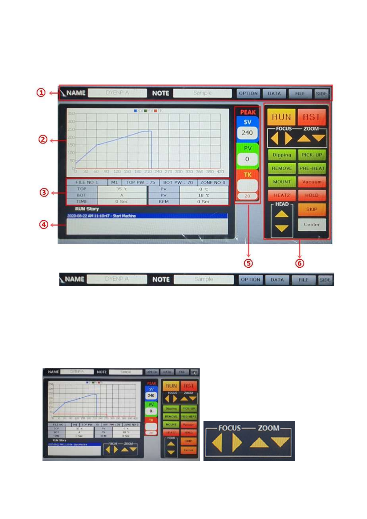
5. Controller Screen
①
NAME: Name of a file which is currently in operation is displayed in text on a screen.
NOTE: Memo is displayed in text.
OPTION: Possible to change options of the device. Vision calibration, temperature correction by mode,
communication environment setting can be changed. This function is protected with a password. An initial
password is “1234”.
DATA: It is possible to analyze a period of time by heating section of the profile which has been created.
Enter the temeprature range to be analyzed.
FILE: It is for controlling the temperature profile. It is possible to create, delete and edit the temperature
profile as well as file number.
SIDE: A button to show or hide the window for controlling the zoom and focus of the side camera.
IR AUTO BGA Rework Station TR3000-IRV
Kukjetrading Co., Ltd.
15
②
Graph Window: Graph in blue [SV] is a graph for the profile which is currently set. Graph in green[PV]
is a temperature control profile for an infrared sensor or K sensor of M4 which is currently in operation.
Graph in red [TK] is displayed when a K sensor is accessed to the TK and it is for measuring the actual
temperature profile.
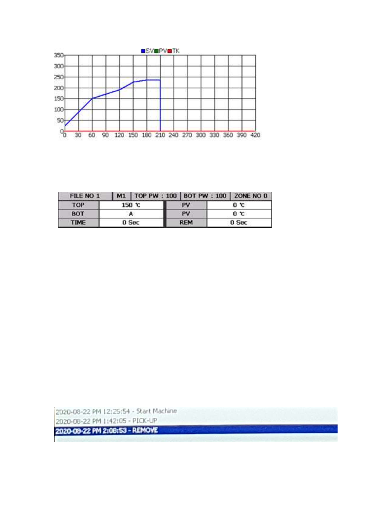
③
FILE NO # : The file number is 1. Up to 100 files from 0 to 99 can be used.
M #: The operation mode number is 1. There are 4 operation modes- 1, 2, 3 and 4.
1~3are control modes using a non-contact infrared sensor and M4 is an operation mode using a contact K
sensor.
TOP PW: It display the output of the Top Heater. Standard is 70.
BOT PW: It display the output of the Bottom Heater. Standard is 100.
ZONE NO 0: It indicates a ZONE number. The zone number shown in this table is 0. As for the zone,
there are 9 levels from 0 to 9. ZONE. In general, zones 0~5 are used. If necessary, levels can be extended.
TOP: Top temperature which has been set. The available temperature range is 0 to 290 Celsius degrees.
PV: Actual upper temperature.
BOT: Bottom temperature which has been set. The available temperature range is 0~499 Celsius degrees.
When it is set as 500, ‘A’ is displayed. ‘A’ is the auto mode for automatic operation at up to 350 Celsius
degrees. When 500 Celsius degrees is entered at the zone 0, it would be applied to all zones. However, if
temperature less than 499 Celsius degrees is entered, the temperature must be entered for each of zones.
The bottom heater is cont
The bottom heater controls with a K sensor and this value indicates the temperature of the heater surface.
This value is the maximum temperature for each zone.
Actual temperature of the PV-bottom heater.
TIME: It displays the time of each zone. It gets down-counted when the operation starts.
REM: It displays the total operation time. It gets down-counted when the operation starts.
④