200823.TR3000-IRV English Manual.pdf - 第29页
IR AUT O BGA R ework S tation TR3000-IRV Kukjetrading Co., Ltd. 29 ② After adjusting positio n s of parts and a PCB t o b e in ali g nme nt, click a “MOUNT” bu tton. Then, a vi sion camera moves b ack to its origin al po…
IR AUTO BGA Rework Station TR3000-IRV
Kukjetrading Co., Ltd.
28
⑤ Adjust XY-axis fine adjusting screws and a rotation handle to align the PCB surface where the parts
would be placed onto with the parts to be placed. With functions including the brightness control for
top/bottom lighting, zoom in/out and focus, make sure the alignment is made accurately.
⑥ Touch a RUN button. A head descends to mount the parts and execute the soldering. .
6.3.2 Soldering without Dipping
It is for applying gell flux onto the mounting surface of the BGA on top of the PCB for soldering.
① Applying gell flux evenly onto the mounting surface of the BGA with a brush or cotton swab. Apply it
with a brush several times.
② Place parts on a part tray in accordance with the mounting direction and then, turn an adjusting screw to
place the parts on the center and then unscrew the adjusting screw a bit.
③ Click a “Pick-up” button.
④ A vision camera and a top head automatically move to pick up the parts and move to a position to be
waiting for adjusting of the mounting position. On the monitor, the PCB surface and the ball surface of
parts are displayed concurrently.
⑤ Adjust XY-axis fine adjusting screws and a rotation handle to align the PCB surface where the parts
would be placed onto with the parts to be placed. With functions including the brightness control for
top/bottom lighting, zoom in/out and focus, make sure the alignment is made accurately.
⑥ Touch a RUN button. A head descends to mount the parts and execute the soldering. .
6.3.3 SOLDERING with No Use of Vision Function
It is for manually placing parts in alignment with a silk line to execute the soldering without using a vision
function.
① Applying Gell flux evenly onto the mounting surface of the BGA with a brush or cotton swab. Apply it
with a brush several times.
② Mount the parts in alignment with a silk line.
③ Touch a RUN button. A head descends to mount the parts and execute the soldering.
6.3.4 Reheating
It is used for the reheating operation due to cold welding, etc. .
<Warning> Main component for liquid Flux is alcohol. So there is a risk of fire if alcohol does not get
removed. Thus, a RST key must be pressed before operation to remove alcohol by operating a cooling
fan.
① Inject a small amount of liquid Flux into a gap of the BGA (Recommended FLUX: KOKI SV-PBF-304P).
② Mount a PCB onto a Table.
③ Click a center button to move a table to be at a position for heating.
④ Click a center button to restore the table back to its original position.
⑤ Press a RST button to operate a cooling fan..
⑥ Press a RUN button. A head descends to mount parts and the soldering gets executed.
6.4 MOUNT(Mounting Test)
It is used for checking whether parts which have been mounted on a PCB are still in alignment.
① When a Dipping or PICK-UP button is pressed, parts on a part tray gets absorbed and then, it waits at a
position where is for adjusting a vision camera position.
IR AUTO BGA Rework Station TR3000-IRV
Kukjetrading Co., Ltd.
29
② After adjusting positions of parts and a PCB to be in alignment, click a “MOUNT” button. Then, a vision
camera moves back to its original position and a head descends to place parts on a PCB and then, elevates
back to its original position.
③ Check a mounting status to see if the parts are in alignment. If they are off from the intended position,
calibrate them.
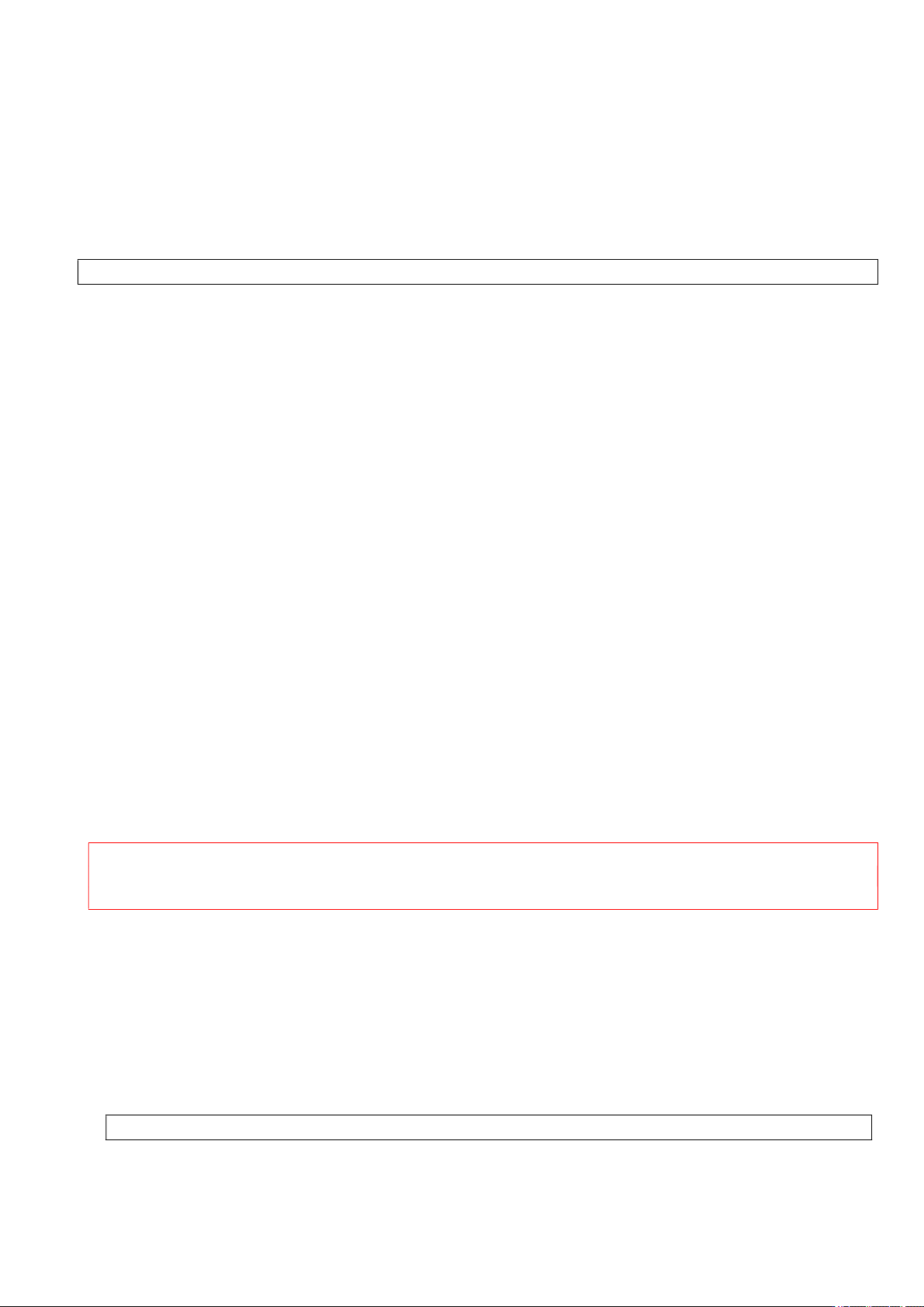
6.5 Vision Calibration
When the device is moved or used for a long period, the location of a vision would not be correct. In the
following case, calibrate the device.
① Place the CALIBRATION JIG on the table and place the BGA in position.
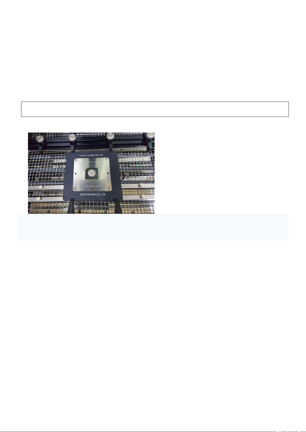
② Press the Center button. The vision camera moves towards the head. While looking at the monitor screen,
align the vacuum bit and the center of the BGA and fix the table.
③ When you press the Pick-up button, the vision camera moves to the left and the head goes down. Vacuum
button turns ON, picks up the BGA, and moves up to the origin. The VISION camera moves to the right and
IR AUTO BGA Rework Station TR3000-IRV
Kukjetrading Co., Ltd.
30
is positioned between the upper head and the calibration jig, and the head goes down again to stop at
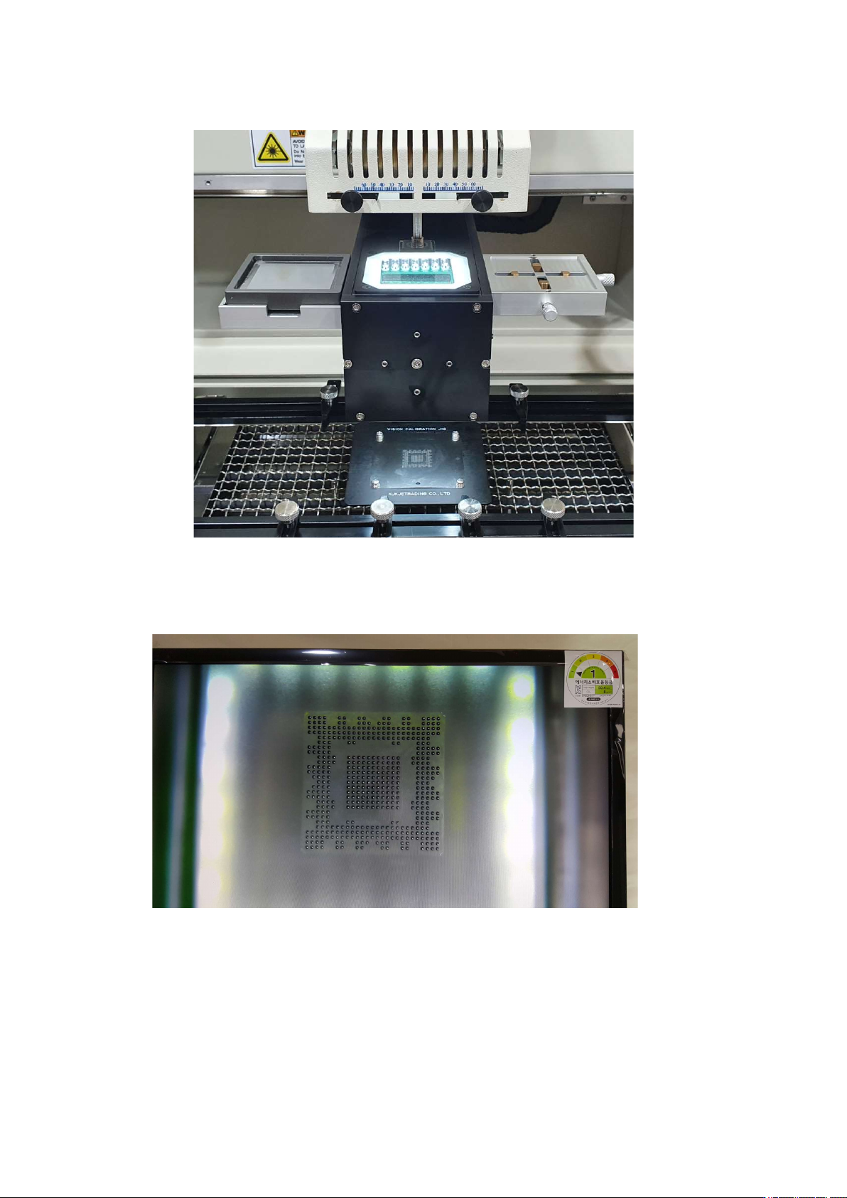
④ Check through the monitor whether the position of the video is correct. Press the up and down buttons of
the head motor to move the head up and down. Set the 1 to 1 distance so that the pattern and the ball are the
same size.
⑤ If the position is out of position as shown below, start adjustment. First, loosen the middle fixing screw a
little and move the adjustment screw to align the image. Loosen one screw a little first, then tighten the
screw on the other side in a symmetrical vertical direction. Excessive adjustment may break the inner