200823.TR3000-IRV English Manual.pdf - 第31页
IR AUT O BGA R ework S tation TR3000-IRV Kukjetrading Co., Ltd. 31 mirror o r wear out the threads. Whe n all adjustments have been made, fix the setscrew again . ⑥ W hen you press the MOUNT button, the v ision returns t…
IR AUTO BGA Rework Station TR3000-IRV
Kukjetrading Co., Ltd.
30
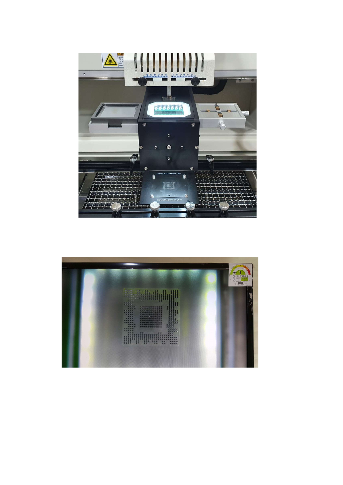
is positioned between the upper head and the calibration jig, and the head goes down again to stop at
④ Check through the monitor whether the position of the video is correct. Press the up and down buttons of
the head motor to move the head up and down. Set the 1 to 1 distance so that the pattern and the ball are the
same size.
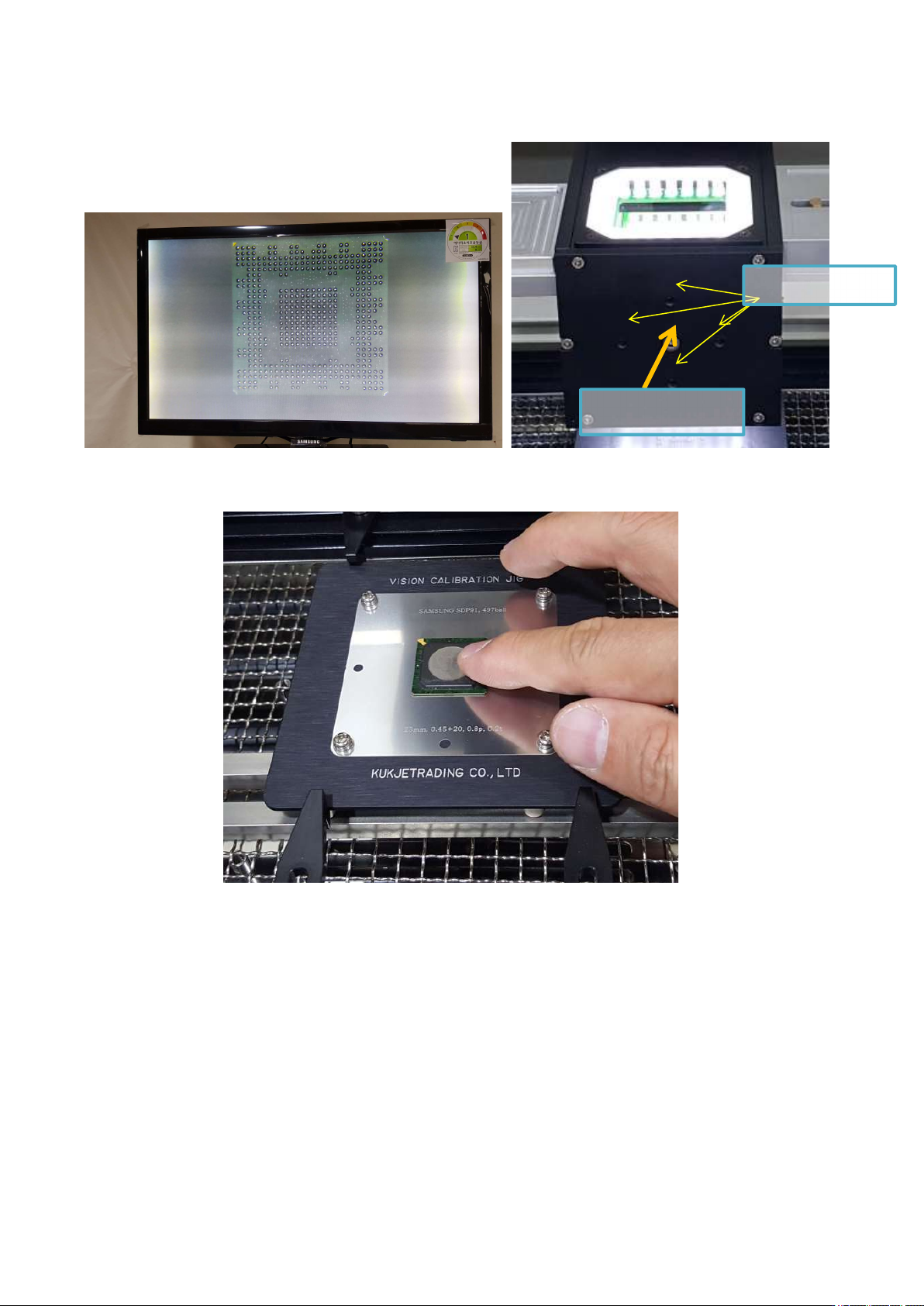
⑤ If the position is out of position as shown below, start adjustment. First, loosen the middle fixing screw a
little and move the adjustment screw to align the image. Loosen one screw a little first, then tighten the
screw on the other side in a symmetrical vertical direction. Excessive adjustment may break the inner
IR AUTO BGA Rework Station TR3000-IRV
Kukjetrading Co., Ltd.
31
mirror or wear out the threads. When all adjustments have been made, fix the setscrew again.
⑥ When you press the MOUNT button, the vision returns to its original position, and the head comes
down to place the BGA on the jig.
Try touching the BGA with your finger to see if the position is wrong. If the BGA is moving, repeat calibration.
Adjust
Screw
Fastening Screw
IR AUTO BGA Rework Station TR3000-IRV
Kukjetrading Co., Ltd.
32
7. Safety Device
If the system provides various safety devices. When a safety function activates, it gets alarmed, and alarming
is displayed on the Run story and power supplied to a heater shuts down. Press a RST button to release
alarming and then, restore back to original conditions. If it does not restore even when a RST switch is touched,
turn off a power switch and then turn it on after a few minutes.
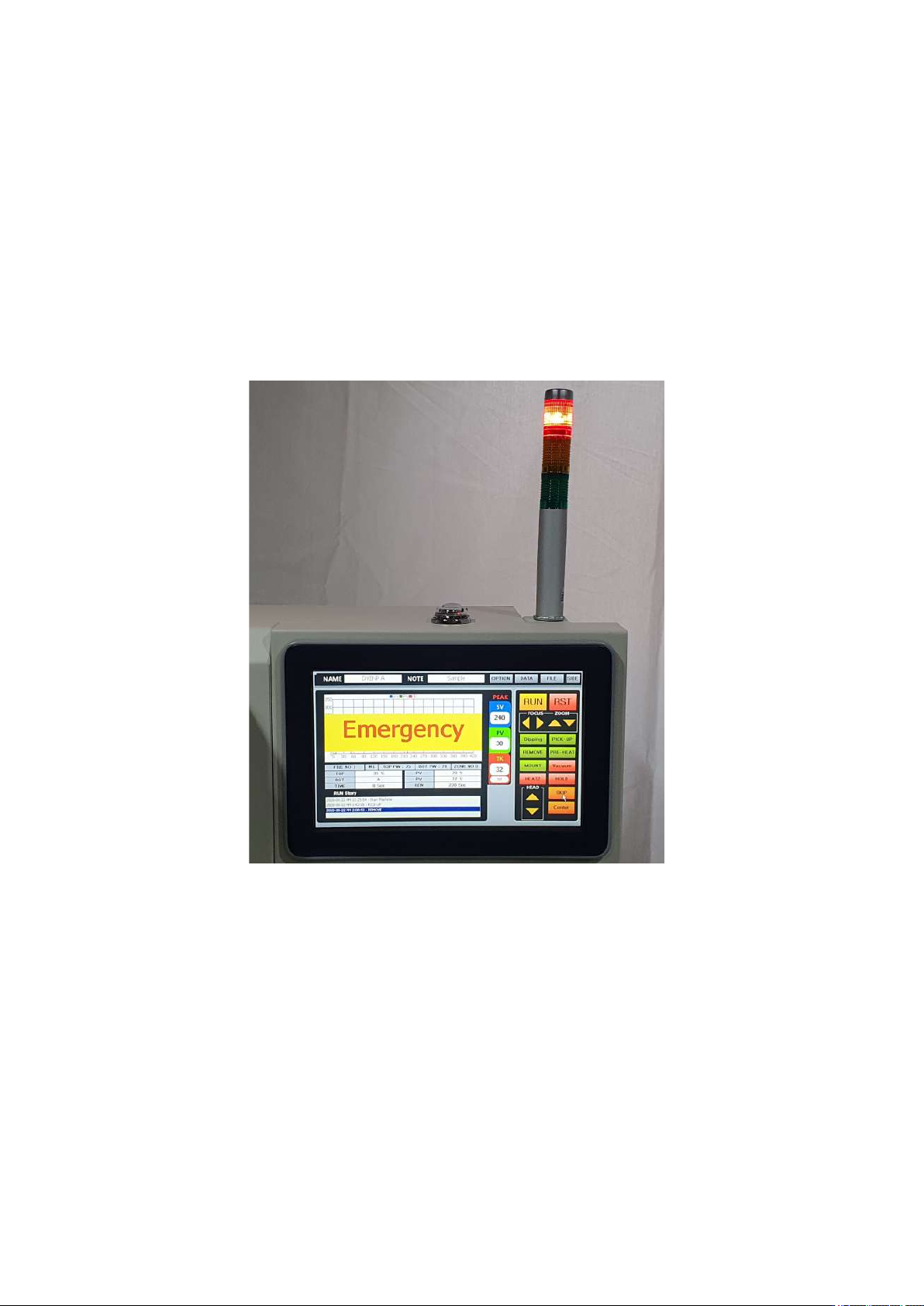
① Emergency Stop
An emergency stop switch is installed in the middle of the front left of the equipment. If this button is
pressed during operation, an emergency warning window blinks on the screen, the power of the heater is cut
off, and the cooling fan is started immediately. When Emergency is released, the equipment returns to the
origin.
② Pickup-Error
In a case that vacuum operates to try to pick up parts but failed or parts are being dropped while the parts
are being picked up, it gets alarmed and power supplied to a heater shuts off.
③ SENSOR FAIL
If a temperature cannot be read due to malfunction of a non-contact infrared sensor, it gets alarmed and
power supplied to a heater shuts off.
④ HEATER - OVER Fail
It gets activated when a temperature exceeds the maximum temperature which has been set by a non-
contact infrared sensor or the measured temperature is more than 290℃ or PCB bottom temperature (TK
temperature) is 260℃. In occurrence of the aforementioned event, power supplied to a heater shuts off.
⑤ HEATER – Running FAIL
While an infrared sensor or M4 mode is on, it gets alarmed and power supplied to a heater shuts off when
a value read by a K sensor drops 10 Celsius degrees than 1 second ago.