200823.TR3000-IRV English Manual.pdf - 第17页
IR AUT O BGA R ework S tation TR3000-IRV Kukjetrading Co., Ltd. 17 PRE-HEA T : When this bu tton is pressed , only t he bo ttom heater starts th e heating and its te mperat ure maintains to be at 250 Celsius degrees. […
IR AUTO BGA Rework Station TR3000-IRV
Kukjetrading Co., Ltd.
16
RUN Story : It displays the operation history. It records operation circumstances in order and when there
is an alarm, the history of alarms would be displayed. When it gets to the last stage, alarm turns on. In
occurrence of error, alarm turns on, and an error message gets displayed on the run story.
It is for displaying the operation history of the device, and this RUN story automatically saves it as a text
file which can be used for finding a cause of a problem.
Operations and alarming messages should be saved as a TXT file by date. .
This file can be saved for 1 month at a minimum and 2 months at a maximum.
As for messages related with the warning, please refer to “7. Safety Device”.
⑤
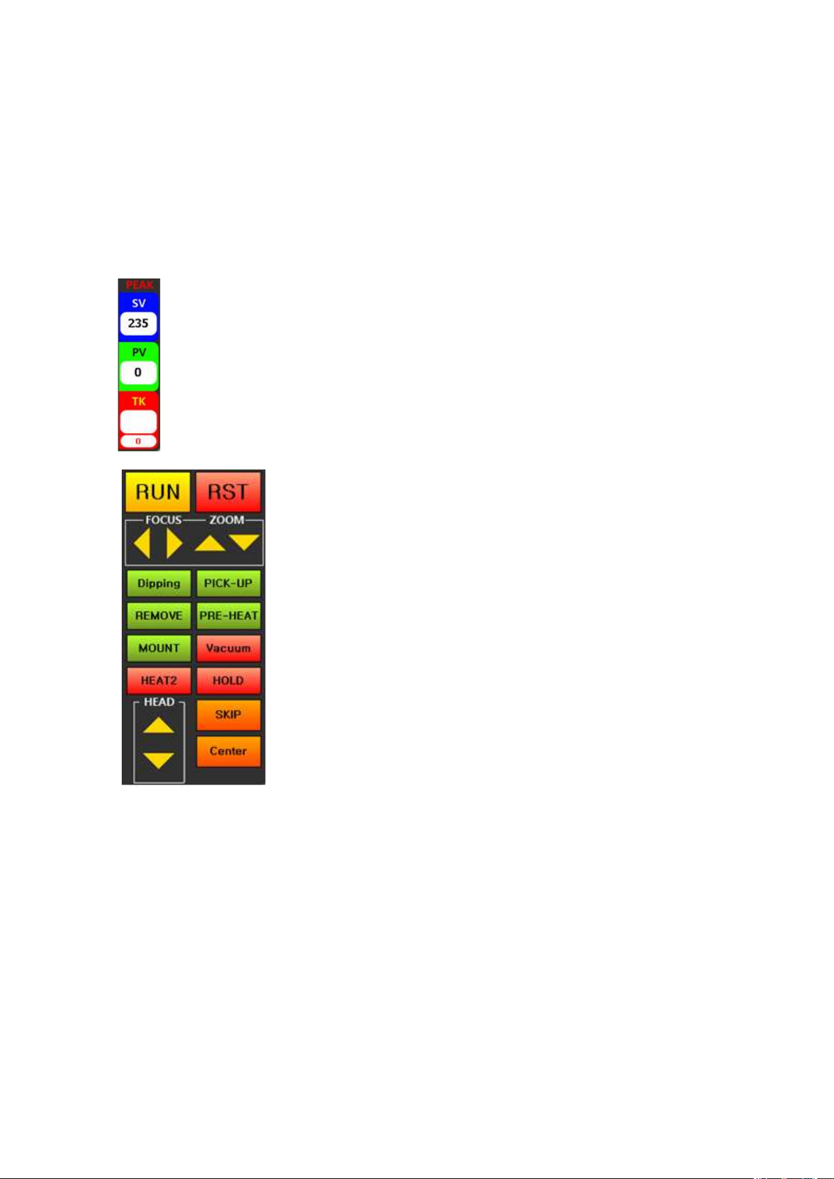
PEAK: It displays peak values for the SV-temperature, PV-
control
temperature and actual temperature measured by a TK-K sensor.
⑥
RUN: It is a button for starting an operation.
When this
button is pressed, a head would des
cend automatically and
an operation
would start with the current temperature profile.
RST:
It is a reset button. When this button is pressed during
operation, the operation would get canceled and a cooling
fan would operate after 7 seconds. During stand-b
y, a
cooling fan can be turned on/off.
Right and left and top and bottom arrows:
<When a vision is being used>
Right and left arrows are for
moving a vision camera right and left, and top and bottom
arrows are for moving a head up and down.
<During heating>
Right and left arrows are for
reducing/increasing the temperature by 1 Celsius degree. Up
and down arrows are for increasing/decreasing time by 5
seconds..
<Stand-By> No Function
Dipping: It is used for dipping into low-viscosity solder or gel flux. After placing a dipping jig onto the
left of a vision head, place a solder and then print. Then, place a BGA on the center of the right side of a
vision head. When a dipping button is pressed, a vision head would move to pick up a BGA and dip it into
solder cream and then place at the center of a vision part.
PICK-UP: After absorbing parts from a part tray, placing them onto the center of a vision part. When flux
is applied on a board, it is easier to pick up parts with a vision.
REMOVE: It is used for removing parts from a board. When this button is pressed, a head automatically
descends until a vacuum bit touches a part and then elevates back to a heating position and starts heating.
If the upper side of the BGA is in a form of a flip chip, there is a high risk of absorption failure when the
absorption position is not accurate. Therefore, a vacuum bit must be adjusted to be at the center upon
descending of the head.
IR AUTO BGA Rework Station TR3000-IRV
Kukjetrading Co., Ltd.
17
PRE-HEAT: When this button is pressed, only the bottom heater starts the heating and its temperature
maintains to be at 250 Celsius degrees. [Temperature which has been set can be changed at the
OPTION.] This function is good for removal of any residual of lead on the PCB of which parts have been
removed. If the ironing operation is executed while preheating of the PCB, the PCB can be cleaned without
any damage on PCB patterns.
MOUNT: When this button is pressed after positioning of parts with the dipping or pick-up function, a
head automatically descends to mount parts on top of the PCB and then restores back to its original position.
Operators should check whether the parts which have been mounted are in alignment. If the parts are not
in alignment, calibration is required.
VACUUM: It is used for manually turning on/off of vacuum. When DIPPING, PICK-UP, and REMOVE
are pressed, vacuum automatically turns on/off.
HEAT 2: It supplies power to all 8 bottom heaters. It is very effective when it is worked with a large board
or residual lead on the PCB is removed by pressing BOTTOM.
HOLD: If you press the botton, the time and temp is holded. If you want to heat contine, you can use this
botton.
SKIP: When this button is pressed, it skips to the last stage. When an operator presses this button after
checking a melting point for lead during operation, it skips to the last stage. For example, if it is currently
in operation by pressing REMOVE, turn on vacuum and remove parts and then, cool it down. When SKIP
is pressed if it is currently in operation by pressing Run, the operation stops immediately and a cooling
mode starts.
Center: It is used for aligning the center of an operation. When this button is pressed, a vision head moves
to be in alignment with a top head. Since a vision image is on the monitor, it gets easier to make a vacuum
bit in alignment with a BGA. When CENTER, or RUN or REMOVE is pressed after the alignment, a
vision head moves back to an original position and the next operation starts.
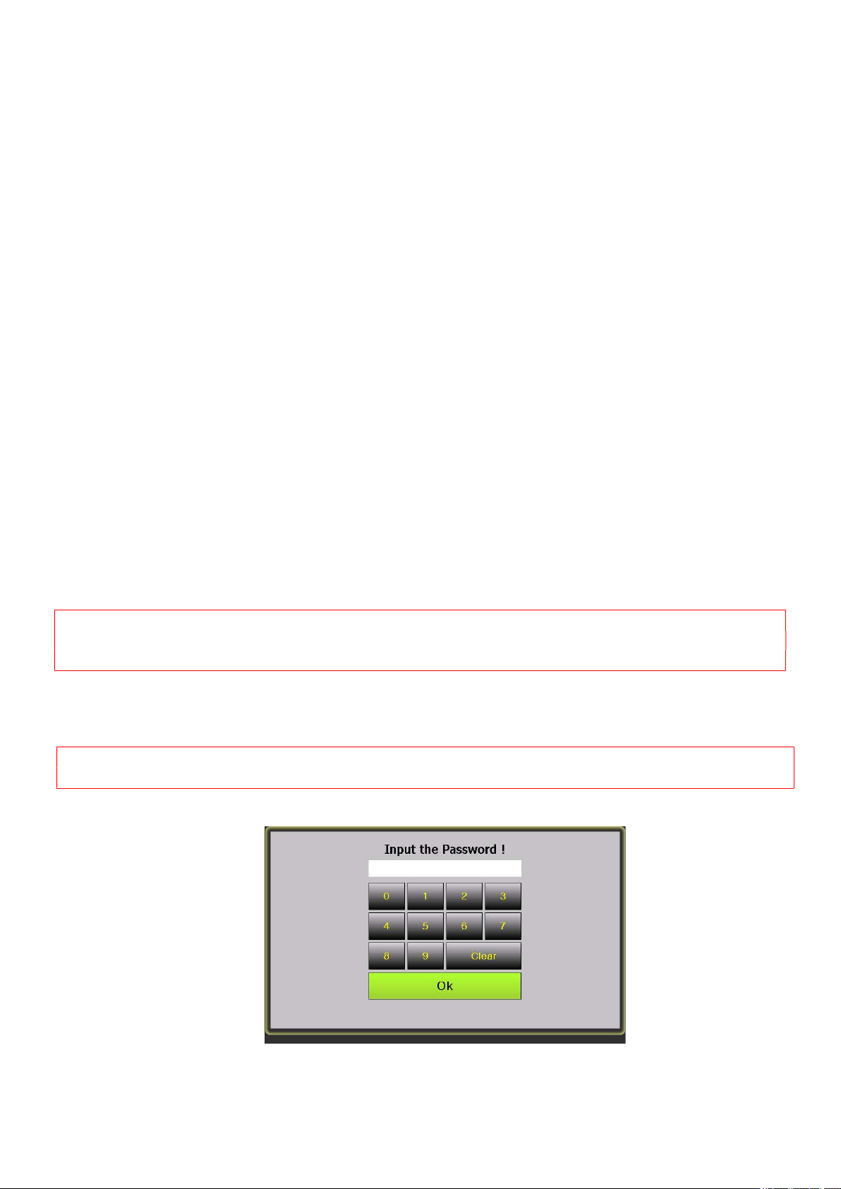
5.1 OPTION ( Setting of equipment)
<Caution>
The device is at factory default setting. If users change settings arbitrarily, there could be a risk of
malfunction. Please fully understand of every function before changing settings.
-. When an option key is touched on the standby screen, the following screen would appear. Then, enter a 4-digit
password. The initial password is 1234.
<Caution> Upon entering of a password, the same button cannot be entered quickly due to delay time. Press
keys slowly.
1234
IR AUTO BGA Rework Station TR3000-IRV
Kukjetrading Co., Ltd.
18
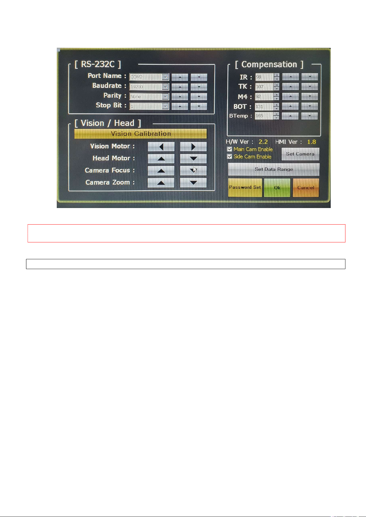
I. RS-232C : Communication Setting
(Caution!: This is for setting of communication conditions of a control board which directly controls an
industrial touchscren PC and equipments. Thus, it should not be changed arbitrarily.
II. Vision / Head : (Note: Currently this feature is not used.)
This part is for calibrating the vision of the device. It operates as follows.
A. Vision Calibration Key :
This key is used for calibrating the vision. When this key is touched, a head lowers down and picks
up parts and then, moves up, and a vision camera moves.
B. Vision Motor ◁ ▷Key :
This key is for moving a start point of a vision part right and left. When the center location of a part
tray is not correct, press this key to adjust the pick-up location.
C. Head Motor △▽ Key :
This key is for adjusting a location to be one on one for a head picking up of a part. When a head is
adjusted up and down, the image size of the BGA would change. Adjust the location to make the image
size to be the same as of a PCB pattern.
D. Camera Focus △▽ Key:
You can use this key for camera focus. But It can't move within auto focus.
E. Camera Zoom △▽ key:
It can adjust zoom for the camera. It use zoom or tele for Image
III. Compensation :
Since an infrared sensor is attached onto the TR3000IRV, the device gets controlled by the
temperature detected by the sensor. The detection area of the sensor is limited to the surface of a PCB
so the temperature detected by the sensor could be different from the temperature of the ball located on
the bottom of a BGA. A difference between the device setting and the actual value of a BGA ball could
be calibrated at this part. This value is expressed in a percentage. Thus, when a value is less than 100,