200823.TR3000-IRV English Manual.pdf - 第7页
IR AUT O BGA R ework S tation TR3000-IRV Kukjetrading Co., Ltd. 7 <Caution > The installation area should be 1,080(w) x 890(d) x 1050(h)mm at a mi n imum. Use more over AC220V 30A for safe. Oulets must be gro…

IR AUTO BGA Rework Station TR3000-IRV
Kukjetrading Co., Ltd.
6
1.2 Specification
1.2.1 Size
Device Size : 640(w) x 710(d) x 1090(h)mm (When a monitor is installed)
Weight: About 86kg
Upper Heater Box Size : 120 x 100 x 50mm
Bottom Heater Inside Size : 320 x 280mm
Installable PCB SIZE: 480x480mm
Available BGA Size : 60 x 60mm(Possible to produce in other sizes)
Monitor Size : 24 Inch 16:9 Rate
1.2.2 Electric Features
Input Power: AC220V 16A at a minimum
Momentary Maximum Power Consumption : 3.1KW+/- 10%.
Upper Heater :About 500W
Bottom Heater :About 2,400W
Monitor and Others : About 200W
Serviceable Temperature (PCB Surface Temperature ) : <290℃
1.2.3 Structure
The upper heater, bottom heater, vision, table and other devices are integrated into the device.
The upper heater head automatically moves up and down by a motor.
Table for fastening the PCB moves in X-axis and Y-axis, and it is also can be adjusted to the minute (+/-
5mm).
Vacuum(Vacuum absorption) is made with the embedded vacuum pump. Compressed air type is an
Optional.
A monitor can be equipped on the left or upper side of the device by the Monitor Mount
The cooling fan are installed in front of the bottom heater box.
On the right side of a vision head, a parts tray is installed and a solder cream dipping zig tray on the left
so parts can be picked up automatically and then a ball of the BGA can be dipped into low-viscosity
cream solder or gel flux.
IR AUTO BGA Rework Station TR3000-IRV
Kukjetrading Co., Ltd.
7
<Caution >
The installation area should be 1,080(w) x 890(d) x 1050(h)mm at a minimum.
Use more over AC220V 30A for safe.
Oulets must be grounded.
A table strong enough to endure the device (Total Weight: 86kg) should be used.
An adjustment foothold, at the bottom side of the device, should be adjusted to maintain the horizontal level
of the device. .
Fastening brackets for a vision and a head must be removed.
A ventilation duct in a shape of roof must be installed on the upper side of the device for emitting soldering
gas.
2. Installation
① Upwrap.
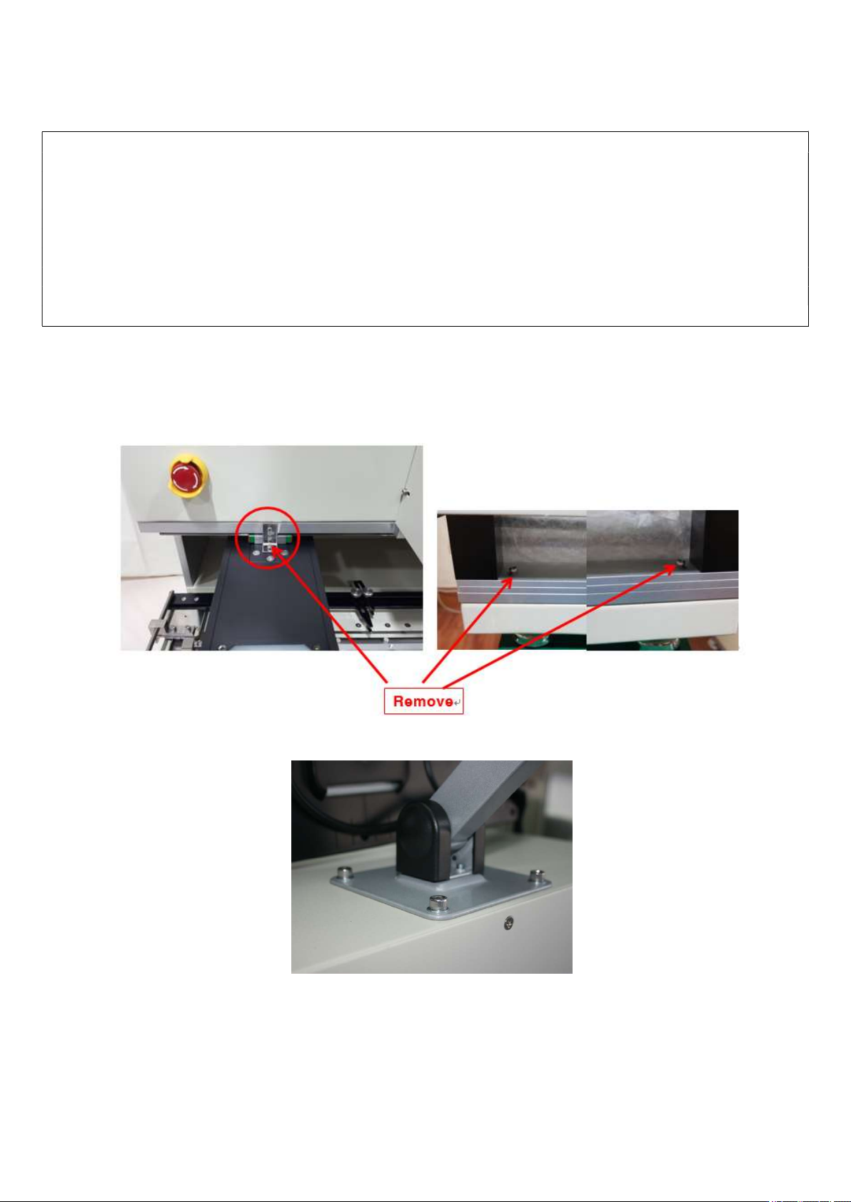
② After placing the equipment on the table, remove the vision fixing bracket and 2 table fixing screws on
the yellow circular display as shown in the picture below.
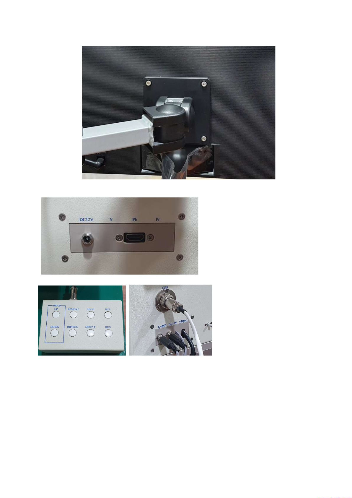
③ Attach a monitor holder. The holder can be installed the upper or left side.
④ Install a monitor.
IR AUTO BGA Rework Station TR3000-IRV
Kukjetrading Co., Ltd.
8
⑤ Connect the power of monitor. Connect the HDMI cable to the monitor and the left side of device.
(Note: DC12V terminal is not connected. Reserved)
⑥ Connect the Remote Control or Mouse. USB port and connector are right side of machine.
⑦ Mount the warp prevent jig on the table.
⑧ Mount Dipping jig on the tray left side of Vision Camera
⑨ Insert external Vacuum pen right side of machine
⑩ Install a vacuum bit. Three type sized are provided.