200823.TR3000-IRV English Manual.pdf - 第6页
IR AUT O BGA R ework S tation TR3000-IRV Kukjetrading Co., Ltd. 6 1.2 Specification 1.2.1 Size Device Size : 640(w) x 710(d) x 1090(h)mm (When a mon i tor i s installed) W ei ght: About 86kg Upper Heater Box Size :…

IR AUTO BGA Rework Station TR3000-IRV
Kukjetrading Co., Ltd.
5
1. Features and Specifications
1.1 Features
① With a vision camera and a monitor, it is possible to mount parts onto the intended location precisely.
② With a dipping button, a ball of the BGA can be automatically dipped into low-viscosity cream solder or
gel flux.
③ With a non-contact infrared sensor or contact k-type sensor, it controls the temperature of the surface of
the PCB to automatically control the device to be in accordance with the preset temperature profiled
regardless of the thickness, material and size of the PCB or BGA.
④ The upper/bottom heater is a far-infrared heater developed by the company
⑤ It can be controlled with up to 10 zones and it can store up to 100 profiles.
⑥ To cope with various PCBs and parts, it has 4 operation modes and it can control the output of the upper
and bottom heater.
⑦ For every operation mode, the AUTO function is allowed. Therefore, the device can be automatically
adjusted onto conditions which have been modified by a user. So it is easy to operate the device.
⑧ The upper control temperature automatically controls the bottom heater.
⑨ It is equipped with a 10 inch industrial embedded touch-screen PC for its HMI.
⑩ It has functions which allow the measurement of temperature profiles and analysis and storage of heating
periods.
⑪ Every alarming event arisen while the device is on is indicated by [Run story] and stored automatically.
Records would be stored for one month and then, deleted in consecutive order to store latest events.
⑫ A vision camera is set to X15 optical zoom. If necessary, optical zoom can be set up to X27 and digital
zoom for X10 (X270 at a maximum).
⑬ ZOOM-IN, ZOOM-OUT and FOCUS controls are available for a vision camera.
⑭ There are various alarming functions for safety. When such functions are activated, there would be an
alarm message and the heater power would be automatically cut off.
IR AUTO BGA Rework Station TR3000-IRV
Kukjetrading Co., Ltd.
6
1.2 Specification
1.2.1 Size
Device Size : 640(w) x 710(d) x 1090(h)mm (When a monitor is installed)
Weight: About 86kg
Upper Heater Box Size : 120 x 100 x 50mm
Bottom Heater Inside Size : 320 x 280mm
Installable PCB SIZE: 480x480mm
Available BGA Size : 60 x 60mm(Possible to produce in other sizes)
Monitor Size : 24 Inch 16:9 Rate
1.2.2 Electric Features
Input Power: AC220V 16A at a minimum
Momentary Maximum Power Consumption : 3.1KW+/- 10%.
Upper Heater :About 500W
Bottom Heater :About 2,400W
Monitor and Others : About 200W
Serviceable Temperature (PCB Surface Temperature ) : <290℃
1.2.3 Structure
The upper heater, bottom heater, vision, table and other devices are integrated into the device.
The upper heater head automatically moves up and down by a motor.
Table for fastening the PCB moves in X-axis and Y-axis, and it is also can be adjusted to the minute (+/-
5mm).
Vacuum(Vacuum absorption) is made with the embedded vacuum pump. Compressed air type is an
Optional.
A monitor can be equipped on the left or upper side of the device by the Monitor Mount
The cooling fan are installed in front of the bottom heater box.
On the right side of a vision head, a parts tray is installed and a solder cream dipping zig tray on the left
so parts can be picked up automatically and then a ball of the BGA can be dipped into low-viscosity
cream solder or gel flux.
IR AUTO BGA Rework Station TR3000-IRV
Kukjetrading Co., Ltd.
7
<Caution >
The installation area should be 1,080(w) x 890(d) x 1050(h)mm at a minimum.
Use more over AC220V 30A for safe.
Oulets must be grounded.
A table strong enough to endure the device (Total Weight: 86kg) should be used.
An adjustment foothold, at the bottom side of the device, should be adjusted to maintain the horizontal level
of the device. .
Fastening brackets for a vision and a head must be removed.
A ventilation duct in a shape of roof must be installed on the upper side of the device for emitting soldering
gas.
2. Installation
① Upwrap.
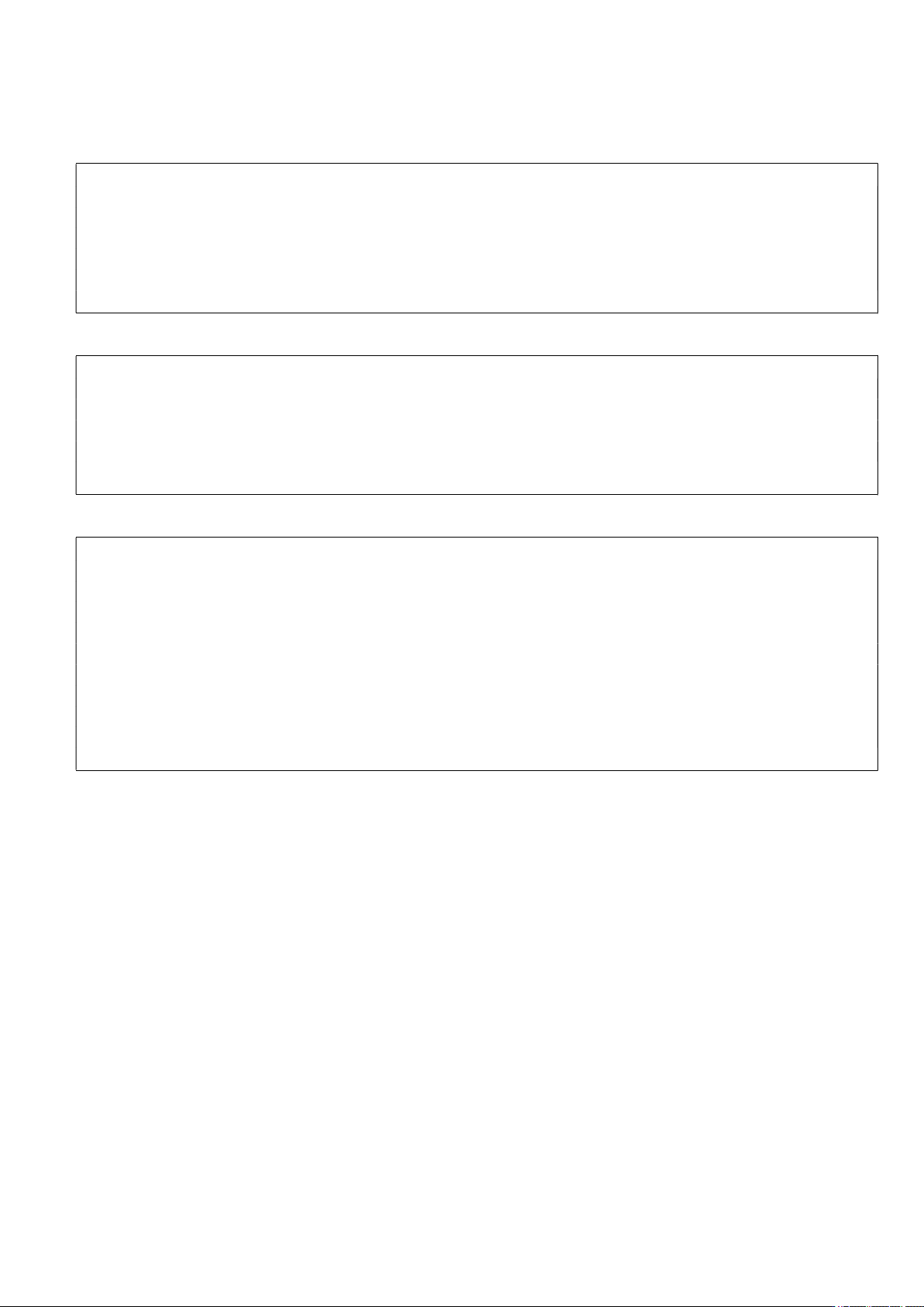
② After placing the equipment on the table, remove the vision fixing bracket and 2 table fixing screws on
the yellow circular display as shown in the picture below.
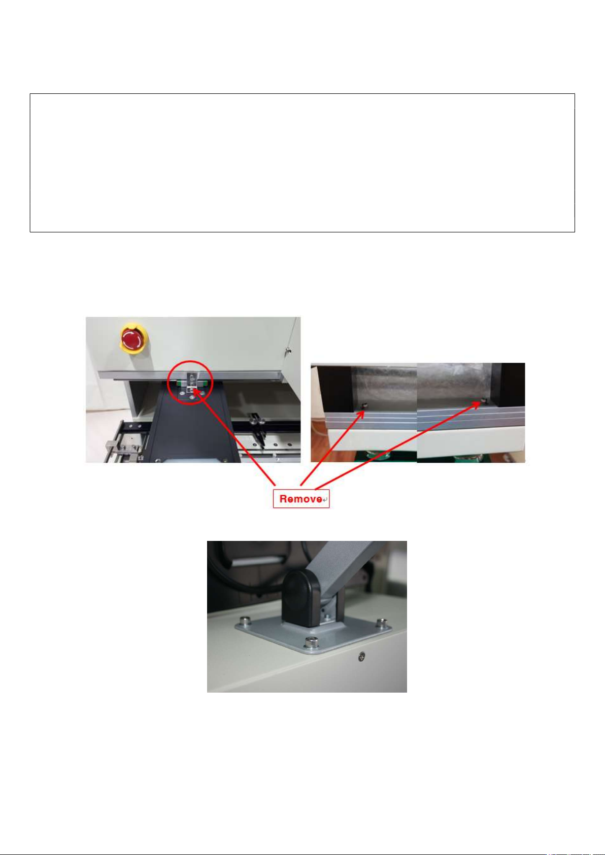
③ Attach a monitor holder. The holder can be installed the upper or left side.
④ Install a monitor.