200823.TR3000-IRV English Manual.pdf - 第25页
IR AUT O BGA R ework S tation TR3000-IRV Kukjetrading Co., Ltd. 25 5.3.2 Switch-Over of T emperature Profile It is for changing the temperature profile number . For inst an ce, if users want to switch over from the file …
IR AUTO BGA Rework Station TR3000-IRV
Kukjetrading Co., Ltd.
24
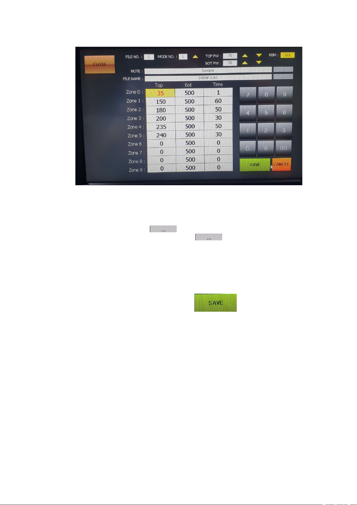
FILE NO: It indicates a file number.
MODE NO: Press UP to select from 1 to 4.
TOP PW: Adjusts the output of the upper heater in the range of 30~100%.
BOT PW: Adjusts the output of the bottom heater in the range of 30~100%.
REM: It displays the total time.
NOTE: It is for a note. Press a button on the right to change its name.
FILE NAME: It indicates a file name. Press a button on the right to change its name.
When it is saved under a different name, all data of the file gets copied and saved.
Top: The available temperature range for the upper heater is 0 to 290 Celsius degrees
Bot: Bottom temperature which has been set. The available temperature range is 0~499 Celsius
degrees. When it is set as 500, ‘A’ is displayed. ‘A’ is the auto mode for automatic operation at up
to 350 Celsius degrees.
Time: 0~999 can be used for each level.
⑤ Enter every desired value to each of zones and then press button to save the entered values. .
IR AUTO BGA Rework Station TR3000-IRV
Kukjetrading Co., Ltd.
25
5.3.2 Switch-Over of Temperature Profile
It is for changing the temperature profile number. For instance, if users want to switch over from the file no. 1 to
the file no. 2, do as follows.
① Press FILE on the upper right.
② Select a file name to be switched over to. Select the file no. 2.
③ Touch a “SELECT” key on the lower center. Then, the file no.2 gets selected.
5.3.3 About Operation Mode
As for an operation mode, there are 4 operation modes. Each mode operates as follows.
① MODE 1 (Temperature Priority Mode )
In the MODE 1, operation starts when a non-contact infrared sensor measures the surface
temperature of a PCB and then it jumps to a zone which has the corresponding temperature range.
When a PCB is hot, the operation period gets shortened and vice versa.
When the surface temperature of a PCB does not reach the preset temperature for the zone 0, it starts
from the zone 0. In the zone 0, only the bottom heater operates not the upper heater.
Starting from the ZONE 1, the whole process gets progressed in accordance with the temperature
and time which have been set. If it fails to reach the preset temperature even a period of time, which
has been set for the corresponding zone, is over, it waits till it reaches the preset temperature and
then moves to the next zone.
Waiting time for each of zones is up to 15 seconds and if it fails to reach the preset temperature even
after that period, there would be alarming and a heater would get turned off. It could happen when
temperature does not rise since the heater is disconnected or the incorrect temperature and time are
entered.
In the MODE 1, a value for the bottom, which has been set, for each of zones represents the
maximum value, and a temperature for the bottom is controlled in accordance with the control
temperature for the bottom. In other words, even if a value for the bottom is set high, it still gets
controlled by a temperature for the top.
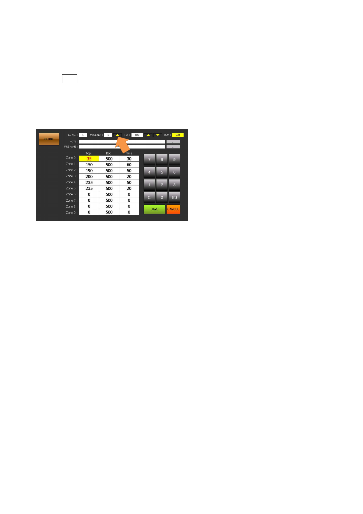
When a temperature for the bottom heater for the zone 0 is set to be 500℃ or higher, values for all
the zones are changed to 500. Also, on the stand-by screen, it is displayed as A(AUTO). In the
AUTO mode, a temperature for the bottom heater for all the zones are controlled by temperature of
the top heater by up to 350℃.
② MODE 2 (Time Preference Mode )

IR AUTO BGA Rework Station TR3000-IRV
Kukjetrading Co., Ltd.
26
In the mode 2,all the controls are made in the same as in the mode 1. However, when a period of
time for the zone is completed, it moves to the next zone even if a temperature does not reach the
goal temperature.
③ MODE 3 (Special Compensation Mode )
MODE 3is used for ground patterns or BGA operation which has a high reflection rate including
glass and metal BGA. This mode is for controlling temperatures by compensating the infrared ray
release.
This mode is effective for circumstances of which there are frequent errors or temperature does not
rise as expected in the general mode.
If it is used for the general PCB, a board can get burn or damaged. Thus, it should be used
only after setting a profile after measuring a temperature with a thermometer.
④ MODE 4
MODE4 is used when the K sensor on the front of the equipment is attached to the surface near
the BGA on the upper part of the PCB to read and control the temperature.
This is useful when working with a PCB where the size of the PCB is small or it is difficult to
secure the detection area of the infrared sensor due to the structure of the PCB.
When attaching a sensor to the bottom of the BGA, the set temperature is the same. However, if
you install it around the BGA, you need to adjust the setting value lower by 5 degrees, and if you
attach it to the bottom of the PCB, you can use it by setting it higher by 10 degrees. For example,
for a setting of 240 degrees, set it to 235 degrees when attaching around the BGA, and to 250
degrees when attaching to the bottom of the PCB.
If the sensor attached to the surface of the PCB is lifted or dropped, the control temperature may
change, so the sensor must be stably attached to a place where there is no foreign matter.