Board-Inverter-Operation-Manual-REV-F-2.pdf - 第11页
BI2000 Boa rd Invert er Manual Revision F / January 2022 Page 11 of 37 Setup WARNING: These procedures should be done by a qualified person in accordanc e with this manual and applicable safet y regulations. A “qualified…
BI2000 Board Inverter Manual
Revision F / January 2022
Page 10 of 37
Temperature and Humidity
227BOperation and storage should be done at 40–105°F (4–41°C) and low humidity. Do not let
condensation collect on the machine. Install the system on a level surface, away from
standing water, possible over spray, and overhead leaks.
Description of Components
228BThe PVA Board Inverter can process and invert multiple boards. It is SMEMA (Surface
Mount Equipment Manufacturers Association) rated for easy integration into a production
line. The unit is designed to operate with PVA workcells.
229BThe operator can control the system with the user interface. The machine status and error
messages are displayed on the LCD screen and the light tower (optional). Operators must
be trained or have read the manual.
230BAny uses other than listed above could result in a dangerous condition and cannot be
protected against by the safety features installed on the system.
231B
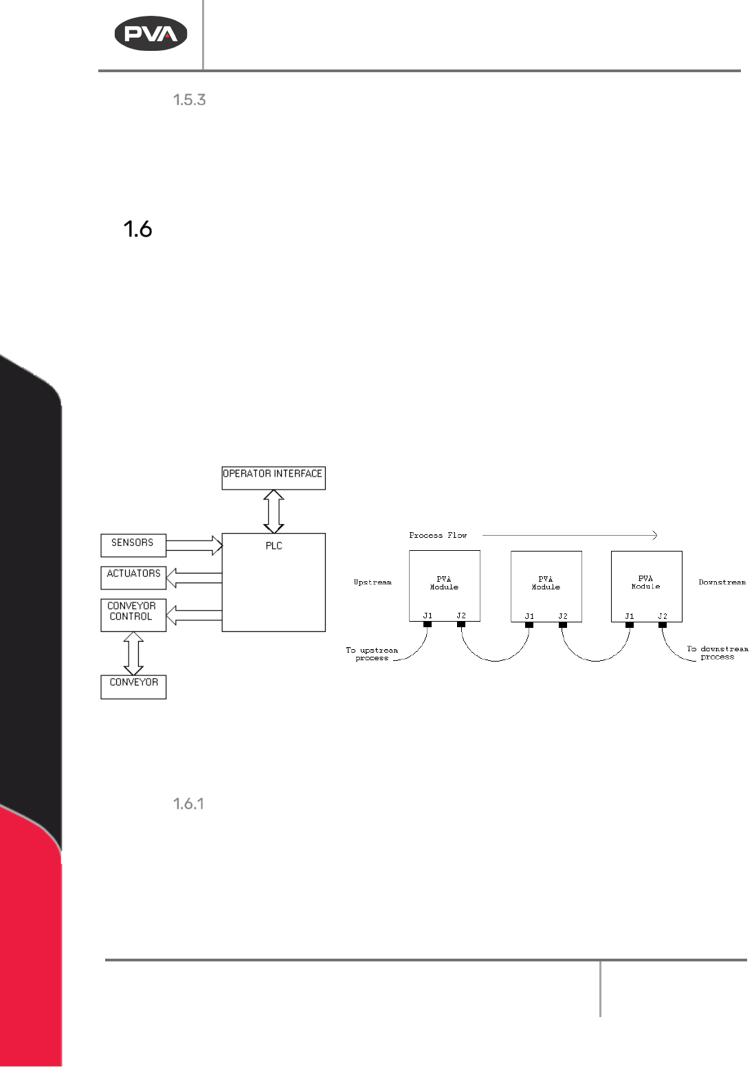
41BFigures 1 and 2: Functional Block Diagram and SMEMA Cables and Process Flow
Hazards Due to Contact
232BThe board invertor is designed to minimize injury from contact with the machine. In certain
modes of operation, you can enter the work area while the module is in operation. Only a
qualified person should do this. Examine warning labels.
BI2000 Board Inverter Manual
Revision F / January 2022
Page 11 of 37
Setup
WARNING: These procedures should be done by a qualified person in accordance with
this manual and applicable safety regulations. A “qualified person” is defined as “a
person or persons who, by possession of a recognized degree or certificate or
professional training, or who, by extensive knowledge, training, and experience, has
successfully demonstrated the ability to solve problems relating to the subject
matter and work.” (ref. ANSI/ASME B30.2-1983.)
Installation
1. 84BPlug the machine into an appropriate power source as shown by the Machine
Specific Information section of the Operating Guide or the legend plate on the
machine. The electrical service should be correctly grounded and the power source
“clean”. If there is high power equipment operating off the same source, a line
conditioner may be necessary. Machine errors can be caused by poor quality power.
WARNING: Failure to comply with electrical specifications can damage the machine
and injure personnel. Electrical hookup must be made by a qualified electrician and
comply with any local standards.
2.
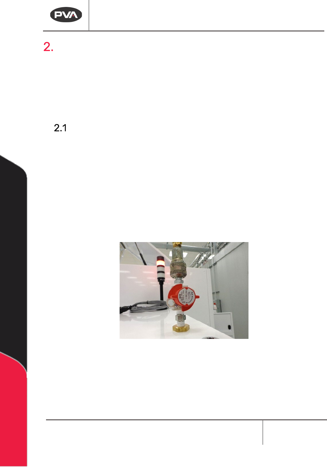
85BConnect the ¼” NPT female fitting at the rear of the machine to a source of clean,
dry air. A hose of ¼” inside diameter is sufficient.
42BFigure 3: Main Air Attachment
3. 86BClose any access doors and engage the “Emergency Stop” button.
4.
87BTurn the red air lockout valve to “SUP”.
5.
88BMake sure any SMEMA cables are correctly connected.
6.
89BTurn the main power to switch “ON”.
BI2000 Board Inverter Manual
Revision F / January 2022
Page 12 of 37
Air Pressure Regulator
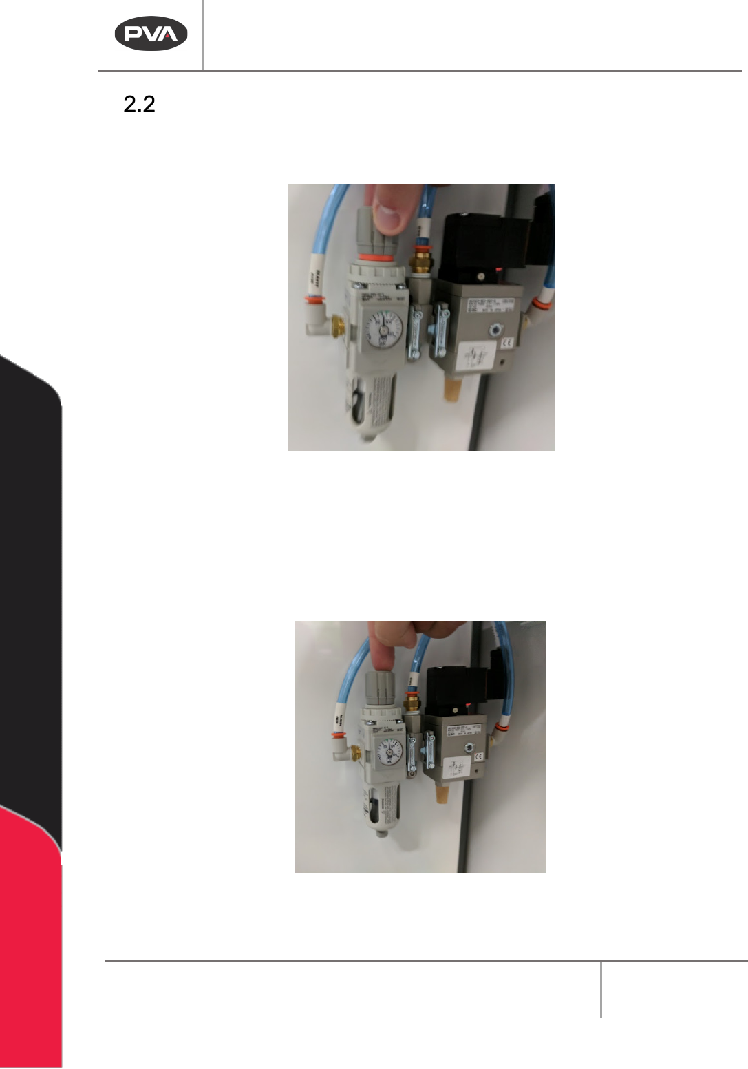
1. 90BTo adjust the system air pressure, pull up on the regulator knob so the orange ring
can be seen.
43BFigure 4: Pull Up on the Regulator to Adjust
2.
91BTurn the knob clockwise to increase the pressure or counterclockwise to decrease
the pressure.
3.
92BWait for the pressure to adjust as shown on the dial.
4.
93BPush the regulator knob down to lock the pressure at the current value.
44BFigure 5: Push Down to Lock