Board-Inverter-Operation-Manual-REV-F-2.pdf - 第15页
BI2000 Boa rd Invert er Manual Revision F / January 2022 Page 15 of 37 Op eration S tart up Pro ced ure 1. 98B Check the air pressure. 2. 99B Close the d oor. 3. 100B Engag e the “Emergency Stop” button. 4. 101B Use the …
BI2000 Board Inverter Manual
Revision F / January 2022
Page 14 of 37
240BState 241BRed 242BAmber 243BGreen 244BBuzzer
245BCycle Stop 246BON 247BOFF 248BOFF 249BOFF
250BAuto Cycle 251BOFF 252BON 253BOFF 254BOFF
255BIn Cycle 256BOFF 257BOFF 258BON 259BOFF
260BMachine Error 261BFLASH 262BOFF 263BOFF 264BFLASH
45BFigure 6: Light Tower & Buzzer Status
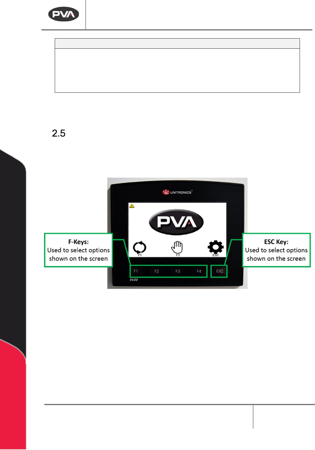
Interface Overview
265BThe operator interface terminal (OIT) has touch screen icons and buttons on the display
that are related to the shown icons. A keyboard or keypad will be shown when a related
value or text field is selected.
46BFigure 7: Pump Components
BI2000 Board Inverter Manual
Revision F / January 2022
Page 15 of 37
Operation
Startup Procedure
1. 98BCheck the air pressure.
2.
99BClose the door.
3.
100BEngage the “Emergency Stop” button.
4.
101BUse the main power red rotary switch to turn on the system power.
5.
102BDisengage the “Emergency Stop”.
Shutdown
267BDo not shut down the machine down with parts in it.
1.
103BWait for all boards to clear the module.
2.
104BPress “ESC” on the OIT. Wait for the Cycle Stop screen to appear.
3.
105BEngage the “Emergency Stop” button.
CAUTION: If maintenance will be done, lockout and tagout the machine.
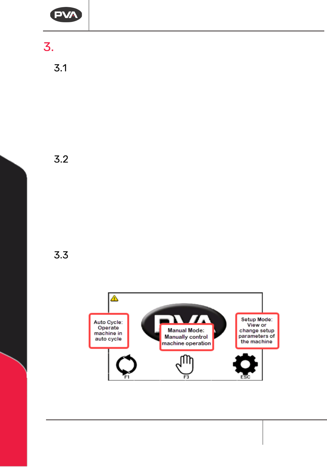
Cycle Stop
268BThis is the default machine state. All other modes are accessed from this screen. To shut
down the machine or select a different operating mode, you must return to Cycle Stop.
47BFigure 8: Cycle Stop
BI2000 Board Inverter Manual
Revision F / January 2022
Page 16 of 37
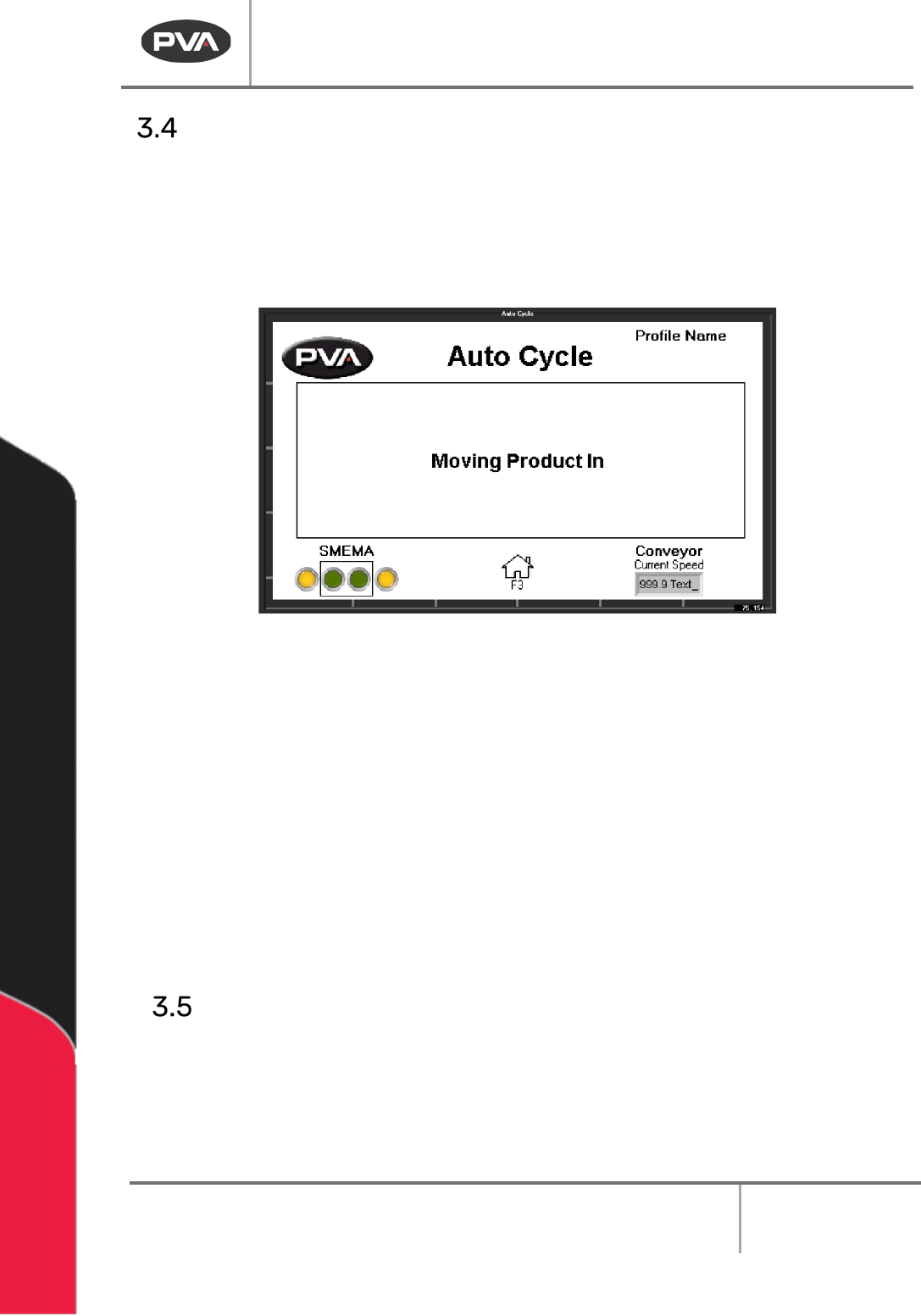
Auto Cycle
270BAuto Cycle is the normal operating mode for the PVA board inverter. In Auto Cycle, the
machine operates as part of a production line and interfaces with any adjacent machines.
1.
106BSelect Auto Cycle from Cycle Stop.
2.
107BPush the “ESC” button to leave Auto Cycle and return to Cycle Stop.
48BFigure 9: Auto Cycle
Note: The board inverter will wait for the boards to exit if there are boards in the
inverter when the “ESC” button is pushed.
3.
108BTo change the settings shown in Auto Cycle, go to Setup Mode.
4.
109BThe Profile is shown above the screen name. Go to Setup mode to change the
profile.
5.
110BThe current conveyor speed is shown.
6.
111BThe text field shows information about board handling and processing.
7.
112BThe SMEMA indicators show the signals being sent and received. Output from the
system are in the box, external signals are outside of the box.
Manual Mode
272BIn Manual mode, the operator has control of the conveyor, flipper, and SMEMA signals.
1.
113BSelect Manual mode from Cycle Stop.
2.
114BUse the “Left”, and “Right” arrow buttons to scroll through the screens.