Board-Inverter-Operation-Manual-REV-F-2.pdf - 第12页
BI2000 Boa rd Invert er Manual Revision F / January 2022 Page 12 of 37 Air P ressu re R egulat or 1. 90B To adjust the syst em air pr essure, pull up on the regulator knob so the ora nge ring can be s een . 43B Figure 4 …
BI2000 Board Inverter Manual
Revision F / January 2022
Page 11 of 37
Setup
WARNING: These procedures should be done by a qualified person in accordance with
this manual and applicable safety regulations. A “qualified person” is defined as “a
person or persons who, by possession of a recognized degree or certificate or
professional training, or who, by extensive knowledge, training, and experience, has
successfully demonstrated the ability to solve problems relating to the subject
matter and work.” (ref. ANSI/ASME B30.2-1983.)
Installation
1. 84BPlug the machine into an appropriate power source as shown by the Machine
Specific Information section of the Operating Guide or the legend plate on the
machine. The electrical service should be correctly grounded and the power source
“clean”. If there is high power equipment operating off the same source, a line
conditioner may be necessary. Machine errors can be caused by poor quality power.
WARNING: Failure to comply with electrical specifications can damage the machine
and injure personnel. Electrical hookup must be made by a qualified electrician and
comply with any local standards.
2.
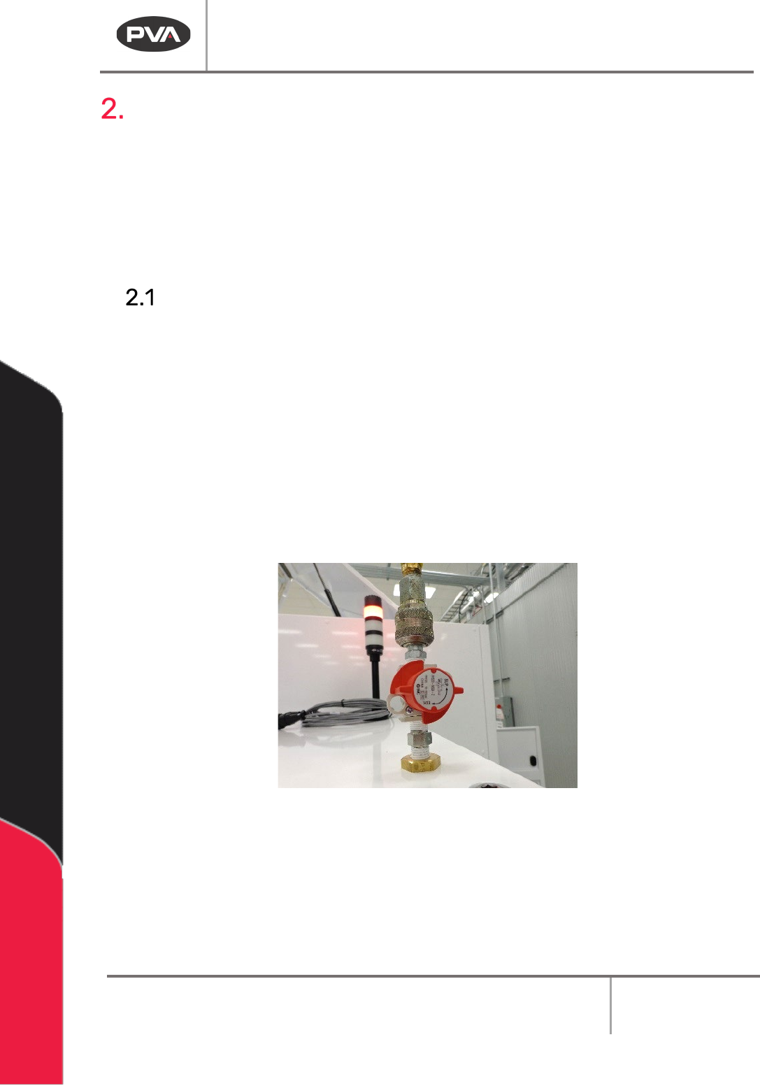
85BConnect the ¼” NPT female fitting at the rear of the machine to a source of clean,
dry air. A hose of ¼” inside diameter is sufficient.
42BFigure 3: Main Air Attachment
3. 86BClose any access doors and engage the “Emergency Stop” button.
4.
87BTurn the red air lockout valve to “SUP”.
5.
88BMake sure any SMEMA cables are correctly connected.
6.
89BTurn the main power to switch “ON”.
BI2000 Board Inverter Manual
Revision F / January 2022
Page 12 of 37
Air Pressure Regulator
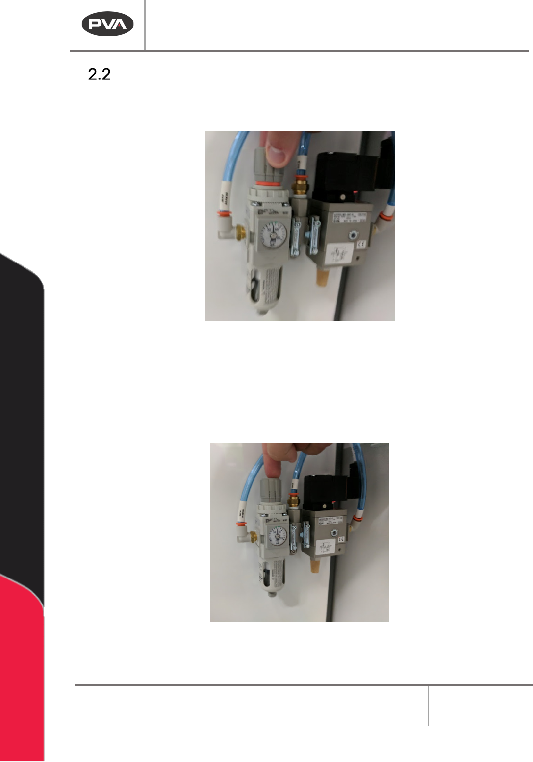
1. 90BTo adjust the system air pressure, pull up on the regulator knob so the orange ring
can be seen.
43BFigure 4: Pull Up on the Regulator to Adjust
2.
91BTurn the knob clockwise to increase the pressure or counterclockwise to decrease
the pressure.
3.
92BWait for the pressure to adjust as shown on the dial.
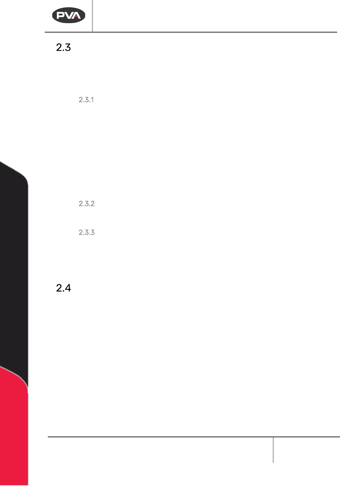
4.
93BPush the regulator knob down to lock the pressure at the current value.
44BFigure 5: Push Down to Lock
BI2000 Board Inverter Manual
Revision F / January 2022
Page 13 of 37
Safety Devices and Guarding
Note: The safety features should NEVER be bypassed, disabled or tampered with.
Precision Valve & Automation, Inc. is not responsible for any damages incurred
because of alteration or destruction of any safety features.
Safety Circuit
236BThe machine main power is controlled by the safety circuit with a safety relay and
additional safety devices. The safety relay has a redundant and self-checking circuit,
which means two parallel relay circuits work together electrically with the safety devices.
The tripping contacts of the relays are connected in series to make sure the safety circuit
will disconnect the power even if one of the relays fails. The self-checking circuit has
positive guided contacts, mechanically forced to operate together. If one of the redundant
relays fails, the power contacts are opened. The safety devices monitor the state of the
Emergency Stop button and other safety mechanisms. When one or more of the safety
devices have opened, the power is stopped.
Work Area Access
237BThe work area is enclosed with Lexan guarding or safety glass.
Door
238BThe top of the machine is protected by a door. The door is monitored by a non-defeatable
limit switch. The Door Bypass key is for maintenance access only.
Light Tower Operation
239BThree stacked indicator lights and a buzzer are used to indicate the status of the machine.
The lights are visible from all sides of the machine and operate as follows:
•
94BThe green light is on when the machine is in Auto Cycle and producing parts. It is
off at all other times.
•
95BThe amber light is on when the machine is in Auto Cycle, but cannot operate
because of an external material handling problem (no incoming parts or no room to
unload parts).
•
96BThe red light is on steady when the machine is not in Auto Cycle due to operator
intervention. It will flash when the machine is in cycle, but the cycle has stopped
because of a machine problem. It will be off at all other times.
•
97BThe buzzer will cycle with the red light during machine errors.