Maintenance (Micron) workbook Iss07.pdf - 第67页
Issue 6, Nov 14 67 Alignment Error Depending on how the pri nter has been set-up for SPC output (p re or post or both), the camera will ca pture each fiducial in turn. This positional data is sent to the computer for it …
66 Issue 6, Nov 14
Objective BT1: Interpret SPC output parameters
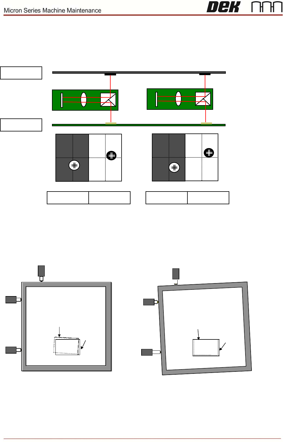
Introduction: screen alignment theory
The camera captures each of the fiducials (screen and board) and sends the data to the
processor. The processor uses this data as well as the calibration data to calculate the
amount of stencil movement required to align the stencil to the board. The processor then
tells the actuators how much to move for this alignment.
BOARD
BOARD BOARD
STENCIL
STENCIL STENCIL
Screen Image
Board
Board
Screen Image
Xr
Xr
Xf
Xf
Y
Y
Screen Image
Board
Board
Screen Image
Xr
Xr
Xf
Xf
Y
Y
Issue 6, Nov 14
67
Alignment Error
Depending on how the printer has been set-up for SPC output (pre or post or both), the camera will capture
each fiducial in turn. This positional data is sent to the computer for it to calculate the x, y and theta alignment
error outputs for SPC analysis.
This data is captured just before the print stroke but after the alignment process if ‘pre’ is selected or after the
print stroke if ‘post’ is selected. This data is captured on both occasions if ‘both’ is selected.
The computer then calculates the alignment error for x, y and theta and sends it out as SPC information.
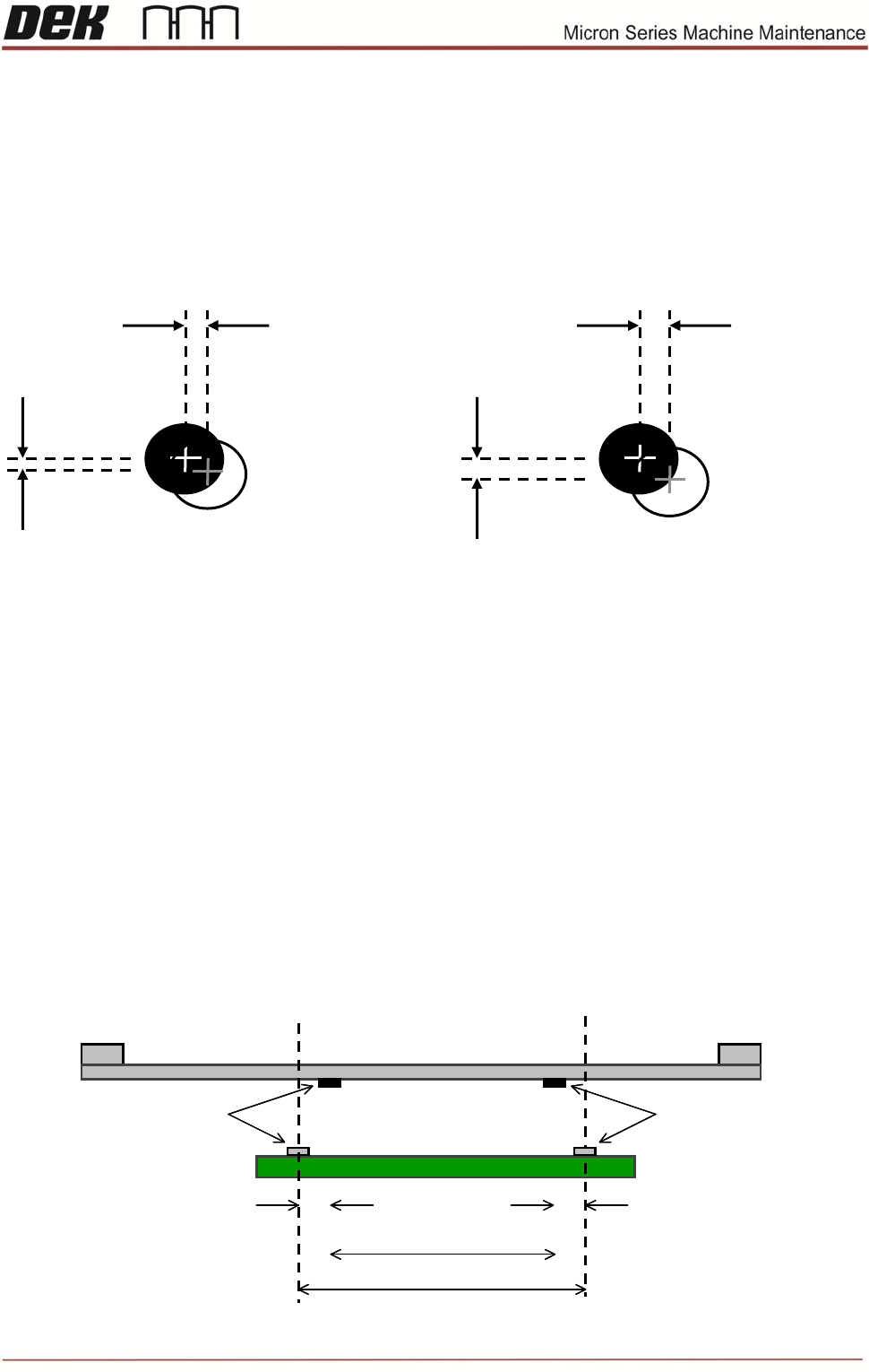
Board Stretch
Board stretch is calculated by taking the point of location of stencil fiducials and calculating the distance
between them. Then the point of location of board fiducials and calculating the distance between them. The
difference between these is board stretch. It will be positive if stencil fiducials are further apart than board
fiducials.
Pre and post fiducial x and y errors are calculated as shown in above diagram by finding positional difference
between each stencil and board fiducial. This can be done either before or after print, but must be done after
alignment. This information is used to calculate x, y and theta alignment data.
This can be illustrated by running several prints with SPC outputs (alignment weighting set to 50%) then
changing the alignment weighting to 100% or 0% and observing the change. If set to 100%, fiducial 1 errors
will move closer to zero and if set to 0% fiducial 2 errors will move closer to zero.
X ALIGN
ERROR
Y ALIGN
ERROR
Y ALIGN
ERROR
FIDUCIAL 2 FIDUCIAL 1
X ALIGN
ERROR
Stencil (mm)
Board (mm)
Fid 2
Fid 1
Fid 2 ‘x’ Error
(Pre or Post)
Fid 1 ‘x’ Error
(Pre or Post)
Stencil (mm)
Board (mm)
Fid 2
Fid 1
Fid 2 ‘x’ Error
(Pre or Post)
Fid 1 ‘x’ Error
(Pre or Post)
68 Issue 6, Nov 14
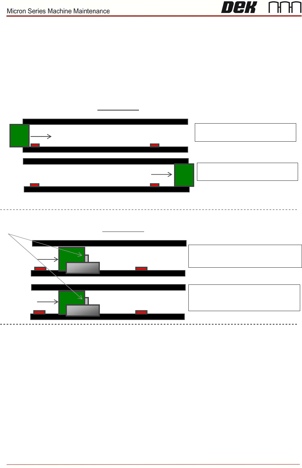
Cycle Time
Cycle time 1 (Left to Right/Right to Left) is time from board being received from Upline to same board being
released to Downline.
Cycle time 2 (Left to Left/Right to Right) is time from board arriving at board stop to board on next cycle
arriving at board stop.
Board Received by Machine
= C
y
cle Time starts
Board Exits Machine
= C
y
cle Time sto
p
s
CYCLE TIME 1
Board Received at Board Stop (1)
= Cycle Time 1 starts
Board Received at Board Stop (2)
= Cycle Time 1 stops and Cycle Time
2 starts
CYCLE TIME 2
Board
stop
CYCLE 1
CYCLE 2