SIPLACE S-23 HM.pdf - 第180页
6 Vision functions User M anual SIPLACE S -23 HM 6.1 The vision systems on the placement system Software Version SR.406.xx 02/00 US E dition 180 6 Fig. 6.1 - 1 Position of the gant ries and DLM1 revolver heads (1) Gantry…

User Manual SIPLACE S-23 HM 6 Vision functions
Software Version SR.406.xx 02/00 US Edition 6.1 The vision systems on the placement system
179
6 Vision functions
6.1 The vision systems on the placement system
The quality requirements concerning the accuracy of automatic placement systems are constantly
rising, for several reasons: 6
– continuing miniaturization of components,
– increasing lead connection density,
– increasing complexity of PCBs and
– increasing component density.
To help meet these requirements, high-precision mechanical components are combined with op-
tical centering and detection systems (known as vision systems) for components and PCBs. 6
The placement system has two gantries (see Fig. 6.1 - 1). On each of these gantries there is a
DLM1 revolver head with a separate component camera system (see Fig. 6.1 - 2). A PCB camera
system is mounted on the underside of the head mount of each gantry (see Fig. 6.1 - 3). 6
Vision analysis units 6
The vision analysis unit plugs into the control unit (see items 1 and 2 in Fig. 6.1 - 4). The compo-
nent and PCB cameras, combined with the vision analysis unit form the vision system. 6
The electrical image signals from the component and PCB camera systems are sent to the vision
analysis unit (see items 1 and 2 in Fig. 6.1 - 4), where the measured values are compared with
the artificial values from the component description or PCB fiducials. The result is used to calcu-
late the correction factors for the individual placement positions. 6
The components are also identified by their package forms. The component is not placed if the
artificial model and the package form measurement do not correspond. 6
The PCB vision system can also be used to detect the position of the feeder modules. Fiducials
on the feeder modules are used to calculate the position deviation of individual feeder modules.
The pick-up reliability can be greatly increased in this way, even for tiny components. 6
6 Vision functions User Manual SIPLACE S-23 HM
6.1 The vision systems on the placement system Software Version SR.406.xx 02/00 US Edition
180
6
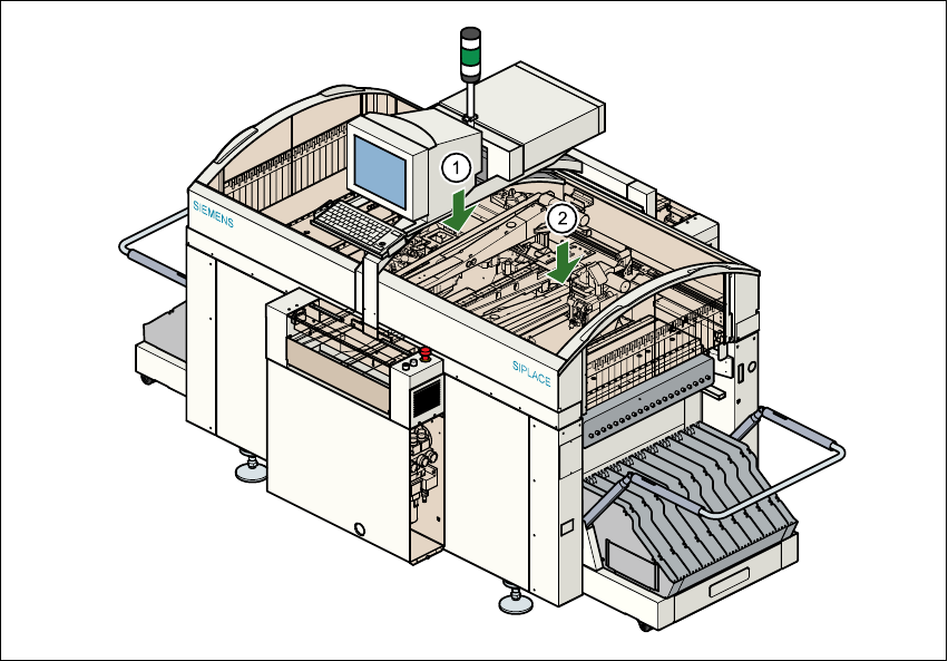
Fig. 6.1 - 1 Position of the gantries and DLM1 revolver heads
(1) Gantry 1 with DLM1 revolver head and component and PCB vision system
(2) Gantry 2 with DLM1 revolver head and component and PCB vision system
6.1.1 Component camera system on the revolver head
The component camera system (see item 2 in Fig. 6.1 - 2) essentially consists of the following
modules: 6
– Lens system
– CCD chip for creating an electronic image of the component
– CCD camera amplifier
– Three illumination planes - flat, medium and steep - for optimum lighting of a wide range of
component shapes
– "Illumination control" board for setting the intensity of the individual illumination planes
User Manual SIPLACE S-23 HM 6 Vision functions
Software Version SR.406.xx 02/00 US Edition 6.1 The vision systems on the placement system
181
6
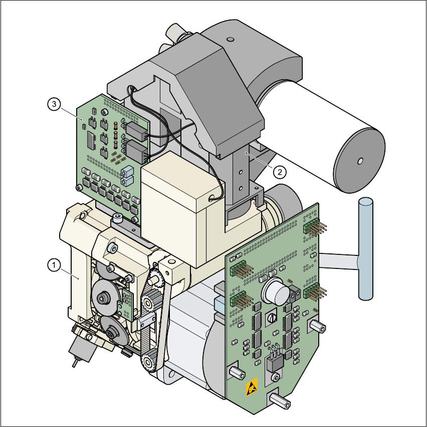
Fig. 6.1 - 2 Component camera system
(1) 12-nozzle revolver head /DLM1
(2) 24 x 24 component camera
(3) Component illumination control board
6
The component camera system is fastened to the top of the revolver head with four hexagon
socket-head screws and is fixed in position with two parallel pins. 6
The component camera system can be used to optically center and place components ranging
from 0402 up to and including SO32 in size. The components, therefore, can vary between
1.0 mm x 0.5 mm and 18.7 mm x 18.7 mm in size and from 0.3 mm to 6 mm thick. The minimum
lead pitch can be as little as 0.5 mm. 6