SIPLACE S-23 HM.pdf - 第407页
User Manual SIPLACE S-23 HM 11 Station extensions / hardware Software Version SR.406.xx 02/00 US Edition 11.5 Ceramic substrate centering 407 11 Fig. 1 1.5 - 2 Cer amic substrate centering (side view) (1) Connecti ng noz…
11 Station extensions / hardware User Manual SIPLACE S-23 HM
11.5 Ceramic substrate centering Software Version SR.406.xx 02/00 US Edition
406
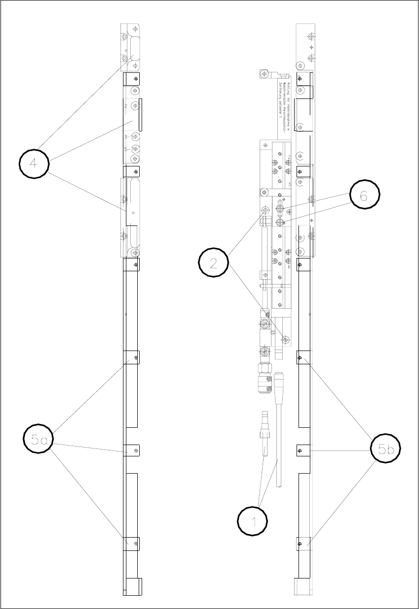
Fig. 11.5 - 1 General overview (plan view)
User Manual SIPLACE S-23 HM 11 Station extensions / hardware
Software Version SR.406.xx 02/00 US Edition 11.5 Ceramic substrate centering
407
11
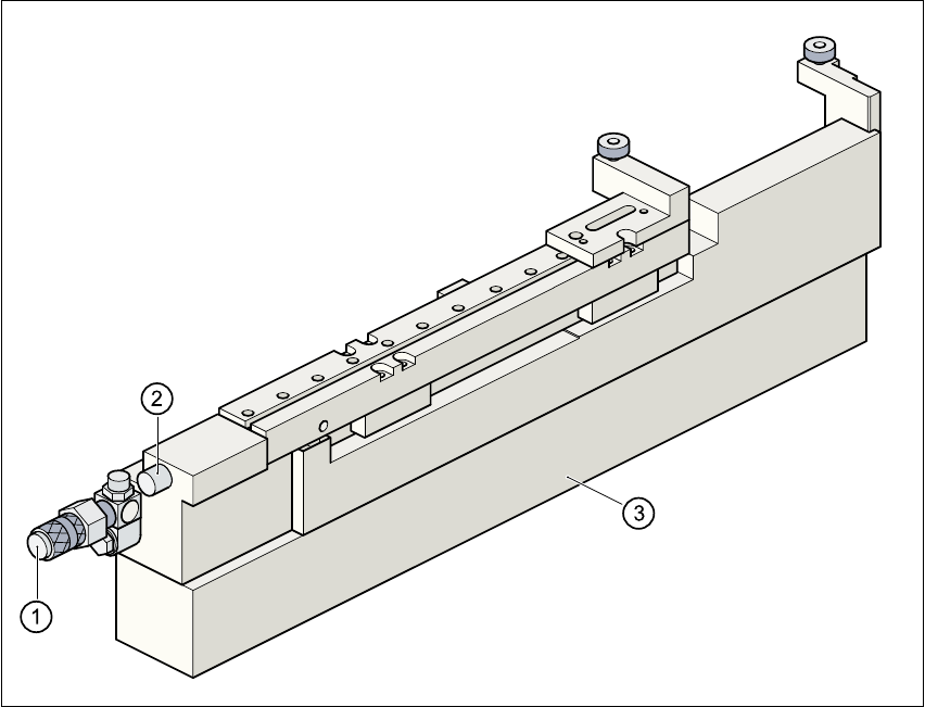
Fig. 11.5 - 2 Ceramic substrate centering (side view)
(1) Connecting nozzle
(2) ‘Ceramic substrate centering’ sensor
(3) Base
11.5.3.3 Maintenance
– Clean and grease the ball race in the X-axis centering unit.
– If necessary, check that the pneumatic driving mechanism is running smoothly.
– The conveyor should be maintained as described in the maintenance instructions.
11 Station extensions / hardware User Manual SIPLACE S-23 HM
11.5 Ceramic substrate centering Software Version SR.406.xx 02/00 US Edition
408
11.5.4 Technical data
11.5.5 Optical centering with oblique lighting
11.5.5.1 General
For optical centering, the special features of the ceramic substrate must be taken into account.
The contrast depends very much on the paste used for the adjustment structure, the clear area
surrounding the adjustment structure, and the type of illumination. 11
The oblique lighting unit is located on the front part of the sub-gantry camera. 11
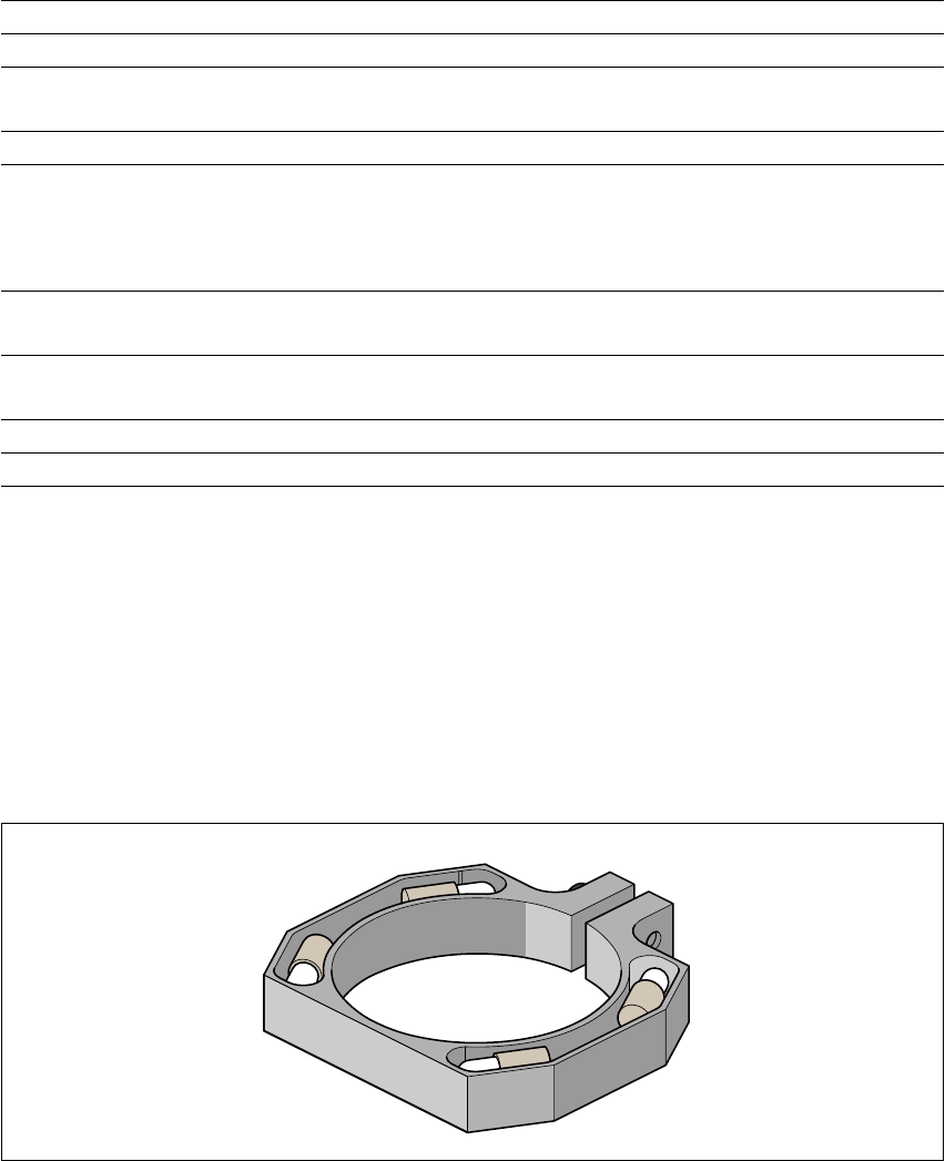
Fig. 11.5 - 3 Oblique lighting unit for the sub-gantry camera
11
Oblique lighting may be switched on instead of the existing lighting (see table in Section Abschnitt
11.5.2). 11
Substrate format 50 mm x 50 mm to 100 mm x 180 mm
Substrate thickness 0.5 mm to 1.5 mm
Substrate model unscribed (without problems)
scribed (requires testing)
Support on the conveyor 2.5 mm
Optical centering: field of view of the PCB vision module
Type of illumination for light pastes:
Type of illumination for dark pastes and close spacing to
adjacent structures (> 1 mm)
5.7 mm x 5.7 mm
PCB vision module (standard)
Oblique lighting (option)
Fiducial criteria See PCB vision module position recog-
nition
Mechanical centering:
X/Y centering accuracy ± 0.07 mm / 4 sigma
PCB underside clearance 12 mm
Compressed air connection 5.5 bar