SIPLACE S-23 HM.pdf - 第273页
User Manual SIPLAC E S-23 HM 6 Vision functions Software Version SR.406.xx 02/00 US Edition 6.6 Test Component 273 The GF or package form fil e is store d in the li ne computer. Basic ally it c onsists of tw o main parts…
6 Vision functions User Manual SIPLACE S-23 HM
6.6 Test Component Software Version SR.406.xx 02/00 US Edition
272
Fig. 6.6 - 24 Test component menu, Evaluat. time video image
Å Press the RETURN key to start the measurement. Once the measuring procedure has ended,
the measuring time in msec is overlaid.
Å Press ESC to leave the option. The video image will disappear and the ‘Test component’ menu
will appear once more.
6.6.4.7 Information on the Group of Edit GF Data Options
The following options belong to the Edit GF data group of options: 6
– Lighting
– Package dimensions
– Lead dimensions
– Ball illustration
– Transformation table
– Select component type (80F machines only)
– Measure mode
GF No. = 5
Evaluation time
Evaluation time [ms] =
RET: Measure component
User Manual SIPLACE S-23 HM 6 Vision functions
Software Version SR.406.xx 02/00 US Edition 6.6 Test Component
273
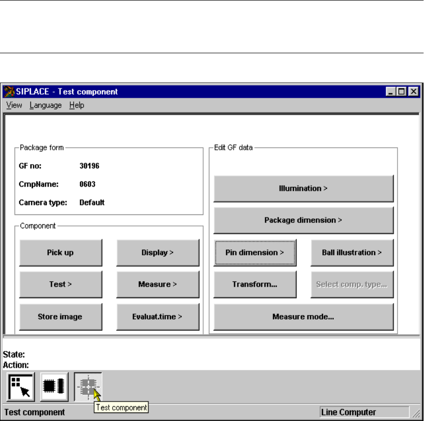
The GF or package form file is stored in the line computer. Basically it consists of two main parts:6
– the geometric package form data and
– the sensor-specific data.
The sensor-specific part contains 6
– the measurement conditions for the component,
– the type of lighting and
– the transformation table data.
NOTE 6
The buttons of the options of the Test component menu will only be active if you have already
loaded a package form. 6
6
Fig. 6.6 - 25 Test component menu, options

6 Vision functions User Manual SIPLACE S-23 HM
6.6 Test Component Software Version SR.406.xx 02/00 US Edition
274
This menu allows you to change 6
– the lead dimensions,
– the package dimensions,
– the ball imaging parameters,
– the illumination parameters and,
– the transformation table.
6
– Lead dimension parameters are
– optical lead length in the x and y directions of the component
– optically lead width in the x and y directions of the component
NOTE 6
The pitch and number of leads can only be changed in the line computer. 6
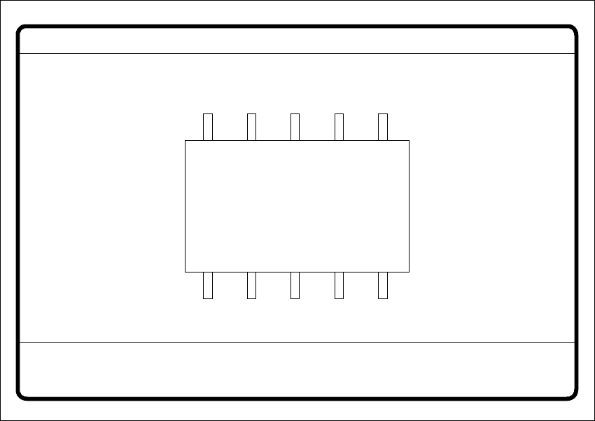
– Package dimension parameters are
– the outside dimensions of the component in millimeters in the x and y directions. Outside
dimensions means the optical dimensions of the component including the lead dimensions.
The geometric dimensions of the leads and component are stored in the GF file in the line
computer. Depending on the geometry of the component and on its illumination by the com-
ponent camera, it is possible that imaging errors may occur. The image does not reproduce
the life-size geometric dimensions but reduces them. This is what is called imaging reduc-
tion. For this reason one refers to the optical dimensions of the leads and component. Set
the component dimensions in a way that they match the visible component outline. The re-
duction factor is entered in the "Real-MA" file. 6
As regards defining the position of the origin of the coordinates system and defining regular and
irregular components, please refer to Section 6.3.2 on page 196. 6
– Ball imaging parameters are
– inner and outer radius type
– inner and outer radius (usually not used)
–contrast
– ball model
– Illumination parameters are
– the contrast in the image