SIPLACE S-23 HM.pdf - 第396页
11 Station extensions / hardware User Manual SIPLACE S-23 HM 11.3 Dual conveyor Software Version SR.406.xx 02/00 US E dition 396 There are two conve yor mode s: "Dual c onveyo r synchr onous" a nd "Dua l c…
User Manual SIPLACE S-23 HM 11 Station extensions / hardware
Software Version SR.406.xx 02/00 US Edition 11.3 Dual conveyor
395
11.3 Dual conveyor
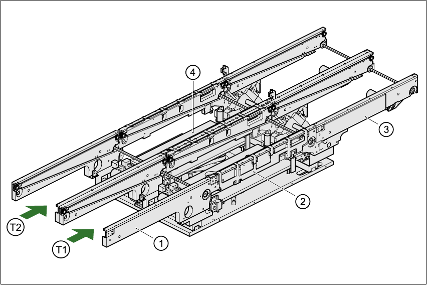
11.3.1 Structure of the dual conveyor
The conveyor belts are driven by DC motors. There is a lifting table for holding the PCBs in each
processing area. The width of the PCB conveyor can be adjusted either via the menu or using the
line computer. 11
11
Fig. 11.3 - 1 Structure of the dual conveyor
11.3.2 General
As the name suggests, the dual conveyor has two transport tracks, which are electrically and me-
chanically independent of one another. In the Standard version, the right-hand side is the fixed
side. There is another version, however, in which the left-hand side is the fixed side. 11
(1) Input conveyor (2) Center conveyor
(3) Output conveyor (4) Lifting table
T1 Transport track 1 11 T2 Transport track 2 11

11 Station extensions / hardware User Manual SIPLACE S-23 HM
11.3 Dual conveyor Software Version SR.406.xx 02/00 US Edition
396
There are two conveyor modes: "Dual conveyor synchronous" and "Dual conveyor asynchronous.
Enter the conveyor mode you wish to use in the machine data (konfig.ma). 11
11.3.3 Defining the transport tracks
The right transport track (viewed in the transport direction) is designated "Transport 1" and the left
as "Transport 2" (see Fig. 11.3 - 1). 11
11.3.4 Changing the conveyor mode
11.3.5 Asynchronous conveyor mode
11.3.5.1 Description
In asynchronous mode, only one PCB in a transport track is processed. At the same time, another
PCB in the second transport track is moved into the placement position. This saves the full con-
veying time of one PCB, thus considerably increasing performance, particularly for PCBs with a
short cycle time. 11
11.3.6 Function
Once the machine has received the job data (cluster, set-up), the PCBs on the feeding belts are
continuously transported to the available center conveyor (provided that the center conveyor is
free) throughout the placement operation. The placement sequence starts as soon as a PCB has
moved onto the center conveyor. The PCBs are processed one after another. 11
PLEASE NOTE 11
The components to be placed and the width of the PCBs must be identical on transport track 1
and 2. 11
If the placement sequence is interrupted, the conveyor interface will be disabled and the PCBs
currently on the center conveyor will be completed. 11
The conveyor interface is disabled or enabled simultaneously for both transport tracks. 11
Conveyor mode Input in konfig.ma
Single conveyor 0
Dual conveyor synchronous 1
Dual conveyor asynchronous 2

User Manual SIPLACE S-23 HM 11 Station extensions / hardware
Software Version SR.406.xx 02/00 US Edition 11.3 Dual conveyor
397
11.3.7 Synchronous conveyor mode
11.3.7.1 Description
In synchronous mode, two PCBs of the same size are moved into the placement position at the
same time. They must be processed as a single cluster. 11
This enables the top and bottom of a PCB to be processed on a single line. This reduces the time
needed to transport the PCBs, since two PCBs are always transported at the same time. 11
11.3.7.2 Function
PCBs on transport tracks 1 and 2 are moved synchronously (i.e. the conveyor belts are indepen-
dent of one another, but are controlled synchronously) on the conveyor sections. The components
to be placed for transport track 1 and 2 must be organized as a cluster in two circuit images (see
the line computer operating instructions). 11
If only one transport track (or center conveyor) is occupied at the start of the placement sequence,
the circuit image for this conveyor section is identified as "do not place". 11
11.3.8 Controlling the dual conveyor with the Single functions menu
Control of the dual conveyor and the Single functions menu are described in section 5 of this user
manual. 11
11.3.8.1 Automatic width adjustment on the dual conveyor
PLEASE NOTE 11
The conveyor setpoint width relates to both conveyor belts. When the command is received, the
conveyor belts are set to the setpoint width one after another.
Automatic width adjustment is deactivated when "synchronous conveyor" is selected. 11