SIPLACE S-23 HM.pdf - 第261页
User Manual SIPLAC E S-23 HM 6 Vision functions Software Version SR.406.xx 02/00 US Edition 6.6 Test Component 261 6.6.4.4 Measure Component Opt ion NOTE 6 This option can only be activate d if you ha ve alrea dy loaded …
6 Vision functions User Manual SIPLACE S-23 HM
6.6 Test Component Software Version SR.406.xx 02/00 US Edition
260
6
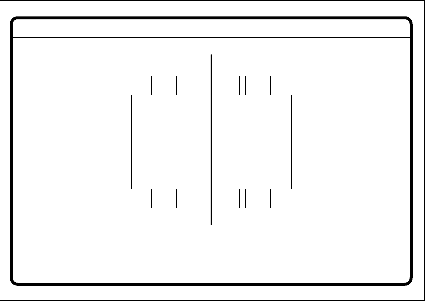
Fig. 6.6 - 19 Test component menu, Test component video image
Å With the Return key you can call all defined individual steps in the measurement procedure
one after the other. Each time you press the Return key another measurement step is carried
out and the results shown on the screen.
Å Use Esc to quit the option. The video image closes and the Test component menu reappears.
GF no. = 5Test component
RET: Test component
User Manual SIPLACE S-23 HM 6 Vision functions
Software Version SR.406.xx 02/00 US Edition 6.6 Test Component
261
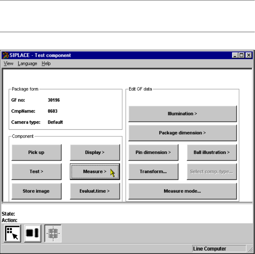
6.6.4.4 Measure Component Option
NOTE 6
This option can only be activated if you have already loaded a package form number and a com-
ponent has been picked up. 6
6
Fig. 6.6 - 20 Test component menu, Measure component option
When this option is activated the following actions are started: 6
– The video image appears on the screen.
– The measurement command is given, using the predefined parameters.
– The MVS performs each component-specific measurement step in turn.
– The measurement values are displayed in the video image.
6 Vision functions User Manual SIPLACE S-23 HM
6.6 Test Component Software Version SR.406.xx 02/00 US Edition
262
6
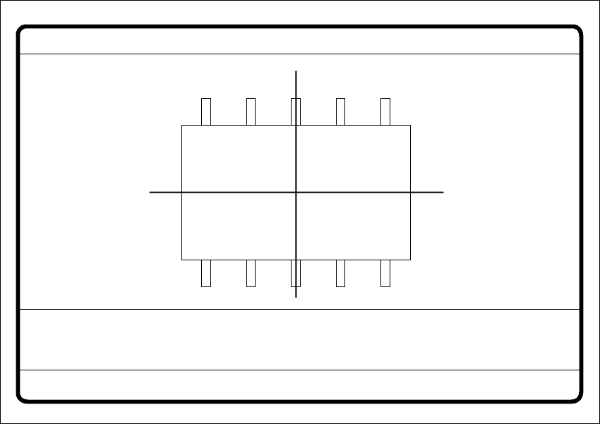
Fig. 6.6 - 21 Test component menu, Measure component video image
Optical surveying of conventional components with lead connections 6
The crosshairs indicate the component’s center. The component outlines are emphasized in
color. 6
The measured values represent the geometric component parameters such as 6
– Lead skew
The value for lead skew will be indicated if you have selected the lead or ball measurement
mode.
–Pitch
The value for pitch will be indicated if the corner measurement mode is active as the last mea-
surement step.
– Number of leads
– x / y offset
– Orthogonality
– Dimensions of the component
–Skew and
Measure component GF No. = 5
X offset = ... Y offset = ... Phi = ...
Orthogon = ...
No. of pins = ...
Quality fact. = ...
Length[mm] = ...
Width[mm] = ...
Spacing[mm] =
RET: Measure component
P.dev.[mm] =