KE-3010A_SPE_EN.pdf - 第18页
- 13 - 4.3. Component place ment Cycle Ti me (The Number of Component to Be Pl aced Per Hour) ① Laser recognition (Unit: CPH) KE - 3010A / 3010AC *7 KE - 3020V A / 3020VRA Reference ra il Front re ference Rear refer ence…
- 12 -
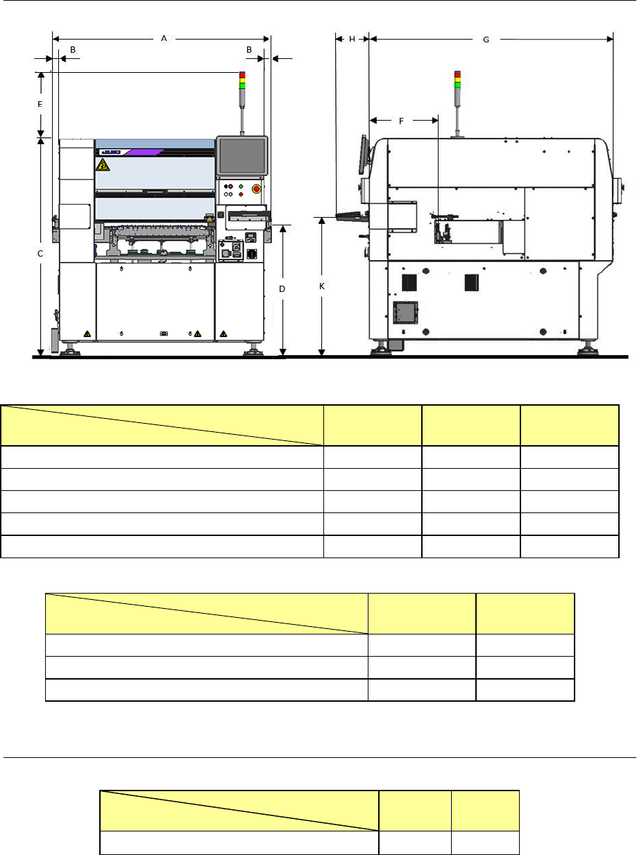
4.2.2. Outside dimension (except for the largest projections)
(Unit: mm)
PWB specification
Dimensions
M PWB L PWB L-Wide
A (transport length) 1,500 1,500 1,800
B (transport output amount) 50 50 200
E(Height of the signal light) 50 50 200
F (PWB transport path from the front side of the cover) 476 476 476
G(Depth of the machine (excluding protrusions)) 484 484 484
* The tolerance of the above dimensions is ±15 mm.
(Unit: mm)
Transport height
Dimensions
900mm 950mm
C (Top surface of the cover from the floor) 1500 1550
D (Top surface of the transport belt from the floor) 900 950
K (Bottom of the keyboard from the floor) 975 1025
* The tolerance of the above dimensions is ±5 mm.
4.2.3. Mass
(Unit: kg)
PWB specification
Model
M PWB L PWB
KE-3010A / 3010AC / 3020VA / 3020VRA 1,850 1,900
- 13 -
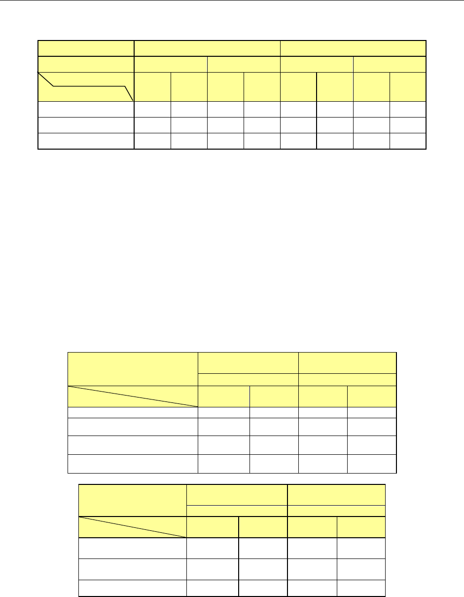
4.3. Component placement Cycle Time
(The Number of Component to Be Placed Per Hour)
① Laser recognition
(Unit: CPH)
KE-3010A / 3010AC *7 KE-3020VA / 3020VRA
Reference rail Front reference Rear reference Front reference Rear reference
PWB size
Component height
M L M L M L M L
6mm 18,500 18,500 17,500 15,500 - - - -
12mm 17,100 17,100 16,500 15,000 17,100 17,100 16,500 15,000
20mm - - - - 15,900 15,900 14,500 14,000
*1: This is the number of components to be placed for one hour when 400 pieces of 0603 and 1005
capacitors are placed onto a 200 mm x 200 mm board at an angle of 0, 90, 180 and 270 degrees
sequentially. (This method conforms to the IPC9850 regulation.)
*2: Electric feeders are used as a component supply device.
*3: KE-3020VA and KE-3020VRA place components in sequence by simultaneous pick-up of the 6 nozzles
of the LNC60 head.
*4: Since the 0402 components require to be placed in the particular sequence, when only the 0402
components are placed the placement cycle time is reduced to approximately half.
*5: For the rear reference, each value indicates the cycle time to be applied when components are placed
from a tape feeder attached on the front side.
*6: The cycle time will take longer by up to 3% when the placement monitor is used. In addition, when the
setting “The system pauses if a component existence error occurs” is enabled, the cycle time will take
longer by up to 30%.
*7: KE-3010AC corresponds only to L board, front reference, component height 6mm specification.
② Image recognition
(Unit: CPH)
Head
KE-3020VA
KE-3020VRA
KE-3010A(MNVC)
LNC60
+
IC head
LNC60
PWB size
Supply form
M L M L
Feeder simultaneous pickup
9,000
9,000
9,000
9,000
DTS 5,100 5,100 5,100 5,100
MTS(TR5SNX) 5,100 5,100 5,100 5,100
MTC(TR6SNV) 1,200 1,200 1,200 1,200
Head
KE-3020VA
KE-3020VRA
KE-3010A(MNVC)
IC head(1 nozzle)
LNC60 (1 nozzle)
PWB size
Supply form
M L M L
DTS
2,200
2,400
2,200
2,400
2,400 2,400
MTS(TR5SNX)
2,100
2,300
2,100
2,300
2,300 2,300
MTC(TR6SNV) 1,300 1,300 ― ―
*1: This is the number of components to be placed for one hour when 36 pieces of QFP and BGA whose
outer dimension is 10 mm x 10 mm or less are placed onto a 330 mm x 250 mm board at an angle of 0,
90, 180 and 270 degrees sequentially.
*2
:
For a tape feeder, it indicates the placement cycle time to be applicable when lead components whose
outer dimensions are 10 mm x 10 mm or less are placed from a tape feeder attached on the rear side.
*3: Component height is 12 mm for M and L machine and 25mm for XL machine.
*4: The time for ATC replacement, board transport and BOC mark recognition is excluded.
- 14 -
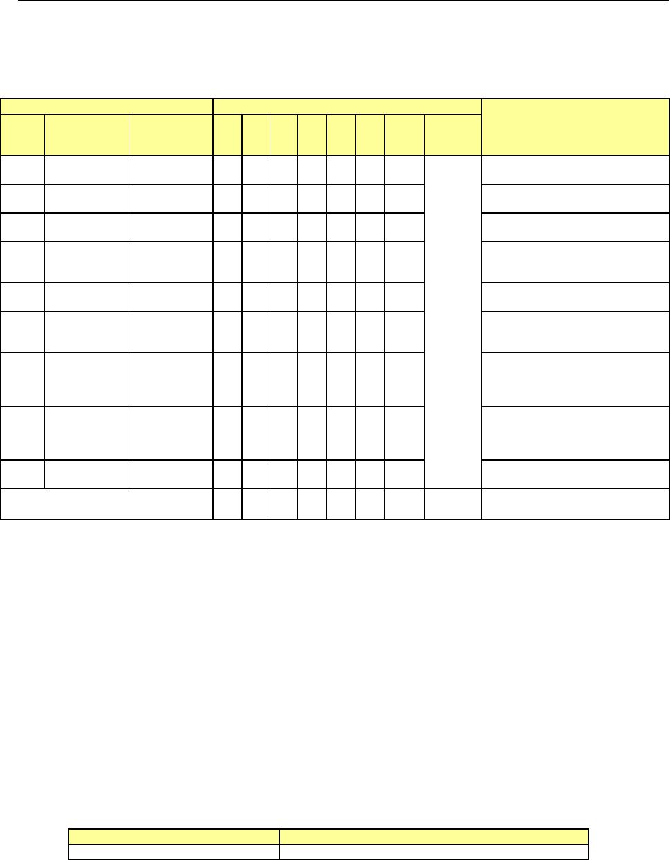
4.4. Nozzles
Various types of nozzles have been designed to increase the reliability of placement of each
type of components as shown in the table below.
You can select one of the nozzle sets shown in Table 1: as the standard nozzles supplied.
Table 1 Nozzles supplied as the standard devices
Nozzle
Nozzle assembly
Applicable components
(reference) and remarks
NO.
Internal
diameter of a
nozzle
External
diameter of a
nozzle
A B D E F G H
Std.
Nozzle
Select
500
2-φ0.4 1.0 x 0.5 − 6 − − − − −
* See
Note 1
1005, 1608, 2012
*See
Note2
SOT (Molding: 1.6 x 0.8)
501
φ0.25 0.7 x 0.4 − − 6 − − −
0603
502
φ0.4 φ0.7 6 − 6 3 − − 3
1005
503
φ0.6 φ1.0 6 − 3 6 3 6 3
1608, 2012, SOT (Molding:
1.6 x 0.8), SOT (Molding: 2.0
x 1.25)
504
φ1.0 φ1.5 − 4 1 3 6 6 3
2012, 3216, SOT23, SOT
(Molding: 2.0 x 1.25)
505
φ1.7 φ3.5 1 2 − 3 3 1 3
Aluminum electrolytic capacitor
(small), tantalum electrolytic
capacitor, trimmer
506
φ3.2 φ5.0 1 1 − 1 3 1 3
Aluminum electrolytic capacitor
(medium),
SOP (narrow type),
SOJ, Connector
507
φ5.0 φ8.5 1 1 − − 1 1 1
Aluminum electrolytic capacitor
(large),
SOP (wide type),
TSOP, QFP, PLCC, Connector
508C
φ8.0 φ9.5 1 1 1 1 1 1 1
QFP, PLCC, BGA
Total number of nozzles 16 15 17 17 17 16 17 15
* Total number of nozzles that can be installed onto an ATC station: 36 pieces (Standard nozzles
34 pieces and up to large-size standard nozzles 2 pieces)
Note 1 As a Std. Nozzle Select, you can select 15 nozzles among those whose number is from 500 to
508C.
However, you have to select a nozzle to be used for calibration of the machine:
・
For laser calibration (one of the nozzle choose from 500, 502 and 503)
・
For image calibration (508C nozzle)
Note 2 Since a theta error may occur due to the shape of the surface of a 2012R component to be picked
up (such as differences of manufactures and/or resistance values), use a No. 504 nozzle if you
have to place 2012R components in the high density (the gap between the adjacent components:
0.3 mm or less).
Limitation on nozzles to be used
(1) Limitation on nozzles used on the LNC60
The LNC60 head cannot be used together with a large nozzle.
(2) Limitation on nozzles used on the IC head side of KE-3020VA
The IC head of KE-3020VA is intended for components of □ 3mm or more. Accordingly,
the following nozzles cannot be used because their nozzle ends are thin. (The IC head
(FMLA) of KE-3020VRA has no limitation for use (except the 509 nozzle)).
Nozzle No. under limitation for use
Standard nozzle
500, 501, 502, 503
Optional nozzles
Other nozzles than the nozzle attached as standard are optional. In addition to the nozzle
dedicated for 0402 (509 nozzle), nozzles matched to different-shape components are prepared.
For details, please ask JUKI sales or dealer.