KE-3010A_SPE_EN.pdf - 第26页
- 21 - L- W ide PWB specifi cation P W B tran sport direc tion Placement di sable r ange 3mm 50 ~ 510mm 3mm 30 ~ 360mm 50 to 250 mm for the a uto PW B width adjusting f unction T ransport rail fix ed side For L - W ide, …
- 20 -
6 mm (Pin diameter + 2.0 mm) *1
6 mm (Pin diameter + 2.0 mm) *1
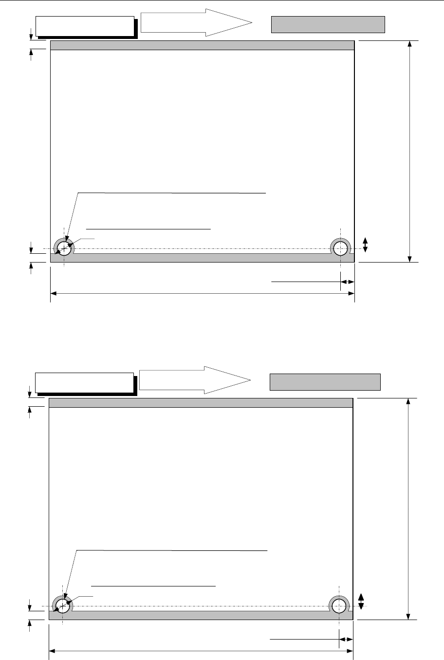
4.7.3. Unavailable areas for placing components on the board
*1: When you select the pin diameter from 1.8 mm to 2.0mm or from 2.5 mm to 4.0 mm, any component
cannot be placed in the area including the pin diameter plus 2 mm. (This rule shall be applied to the
following board type.)
M PWB specification
PWB transport direction
Placement disable range
3mm
5±0.1mm
50
~
330mm
3mm
30
~250mm
50 to 250 mm for the auto PWB width adjusting function
Transport rail fixed side
PWB transport direction
Placement disable range
3mm
5±0.1mm
50
~
410mm
3mm
30
~
360mm
50 to 250 mm for the auto PWB width adjusting function
Transport rail fixed side
L PWB specification
5±0.1mm
5±0.1mm
When the diameter of the reference pin is 4 mm
When the diameter of the reference pin is 4 mm
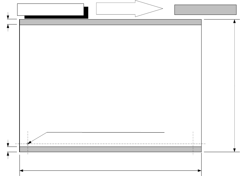
- 21 -
L-Wide PWB specification
PWB transport direction
Placement disable range
3mm
50
~
510mm
3mm
30
~
360mm
50 to 250 mm for the auto PWB width adjusting function
Transport rail fixed side
For L-Wide, the pin standard is not available.
- 22 -
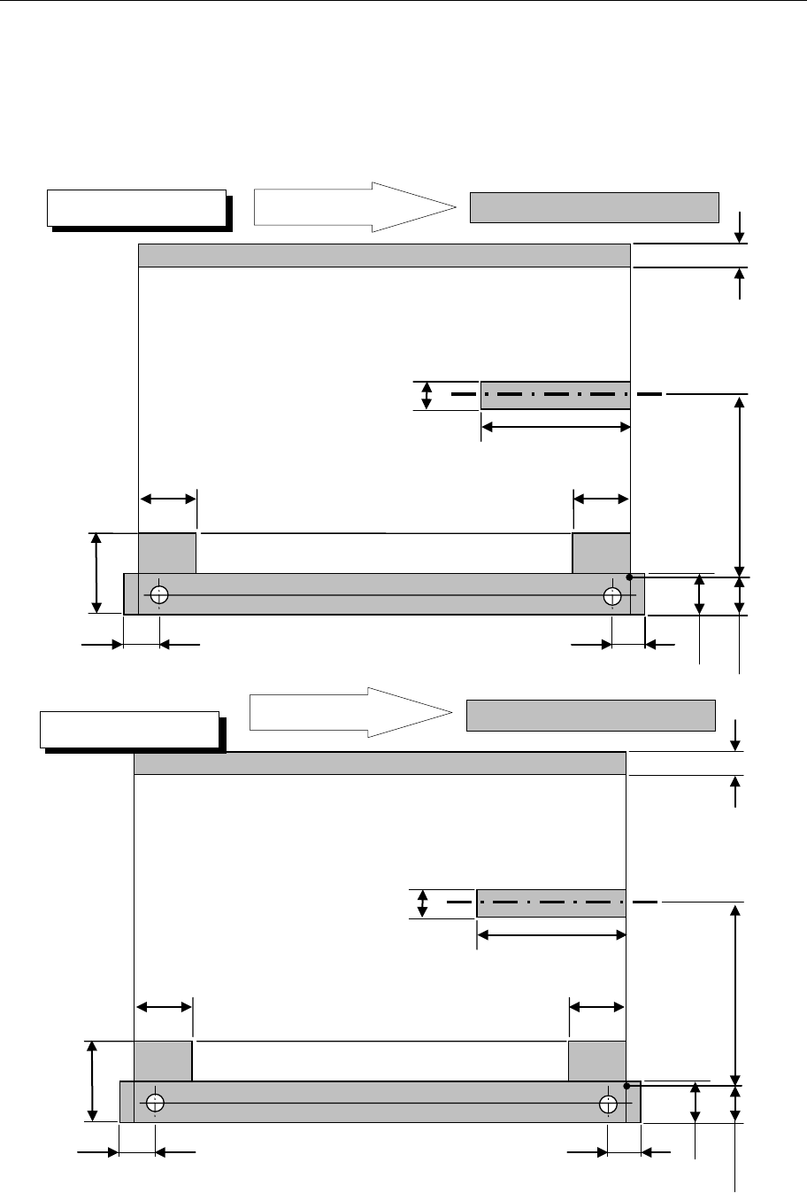
4.7.4. Support pin installation disable range
These dimensions are factory-set ones. The restriction range is added when the
reference pin is used. The PWN transport direction is for a clockwise flow as shown in
the figure. In the case of a flow in the opposite direction, the support pin disable range is
bisymmetrical to the figure.
・PWN bottom drawing
26mm
39.3mm
26.5mm
61mm
26mm
26.5mm
20mm
23mm
22.6mm
0 to 292 mm Moving part
4.5mm
Placement disable range
PWB transport direction
Placement disable range
26mm
39.3mm
26.5mm
61mm
26mm
26.5mm
20mm
23mm
22.6mm
0 to 187 mm Moving part
4.5mm
Placement disable range
PWB transport direction
Placement disable range
M PWB specification
L PWB specification