KE-3010A_SPE_EN.pdf - 第72页
- 67 - 6.7.4. Options No. Name Function/appl icable mo del (Note1) TR5SNX TR5DNX TR6SNX TR6DNX TR7DN ① Inspection conv eyor specificat ion This functio n stop s a P WB on the c onveyor an d inspe cts it v isually . - - ○…
- 66 -
(*1) The following types of tray units (tray bases) on which trays can be set are provided:
Model
Type of a tray unit
Description
DTS
Top plate (ST)
assembly
Top plate on which one tray can be set. (Standard)
Top plate (MTX)
assembly
Top plate on which two or more trays can be set. (Option)
MTS
(TR5SNX/5DNX/7DN)
MTC
Tray unit (ST)
One-touch style of holder unit that
pushes down a tray with its spring
pressure.
A tray can be replaced with another
one easily. (Standard)
When the soft material trays
are used a fixed holder unit
can be replaced from Tray unit
(ST). (Option)
Tray unit (A)
Unit that fixes a tray with screws.
It is appropriate for a tray whose material is soft. (Option)
(*2) When you use a DTS and a tope plate (MTX) assembly, the minimum size is 65 mm (W)
× 65 mm (L). When you use a MTS/MTC and an optional waffle tray holder, the
minimum size is 50 mm (W) × 50 mm (L).
(*3) The thickness is a dimension from the bottom of a tray to the top of the tray or a
component, which is higher. When you use a tray whose thickness is more than 11 mm
with a DTS/MTS, you have to set the feeder float sensor of the mounter so that it cannot
be used.
(*4) When you use a tray whose thickness is more than 9 mm with a MTS or TR6DNV, you
cannot set any tray immediately above that tray.
(*5) The area of a component that can be picked up should be □5 mm or more. For a
mechanically chuck component such as a BGA, this area should be □17 mm to □50
mm.
When the CSP chuck (option) is installed, the mechanical chuck component is □9
mm to
□43 mm.
(*6) This is the mass when the device is equipped with full options.
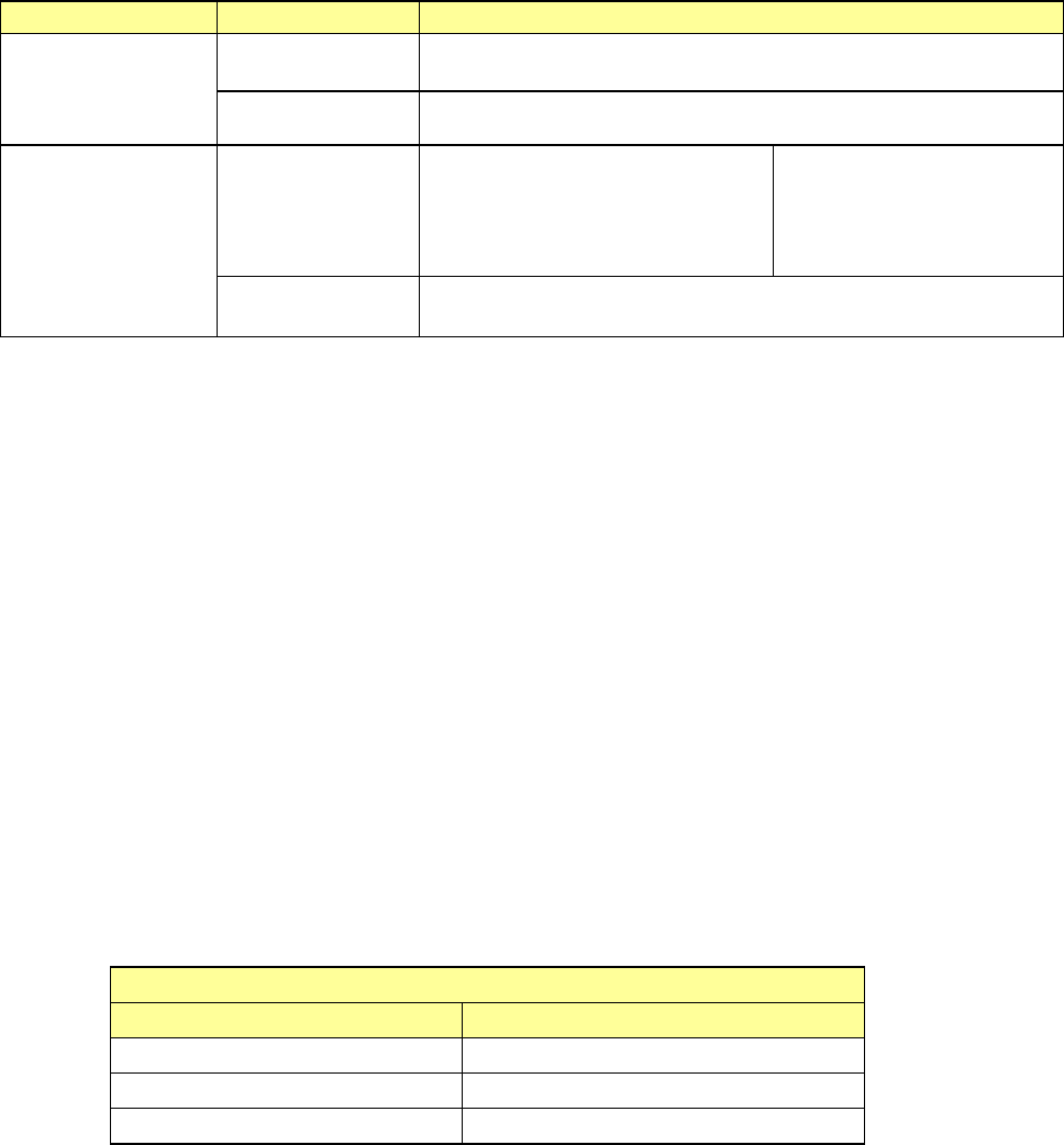
(*7) For the use of the RFID system, the RFID tray bases are required.
Note that the RFID tray bases cannot be shared among the different types of the devices.
The RFID system is a factory-set option. For further information on installing the RFID
option, please contact JUKI or the representative office in your area.
RFID tray base
Representative applicable model Model with compatibility
TR5SNX TR5DNX,TR5SNR,TR5DNR
TR6SNV TR6SNR TR6SNX
TR6DNV TR6DNR TR6SNX
* The standard tray base can be used for all the models mentioned above.
(*8) The tray unit for TR7DN has no compatibility with the existing machine models.
(*9) It does not correspond to the Feeder exchange trolley RF.

- 67 -
6.7.4. Options
No. Name
Function/applicable model (Note1)
TR5SNX TR5DNX TR6SNX TR6DNX TR7DN
①
Inspection conveyor
specification
This function stops a PWB on the conveyor and inspects it visually.
- - ○ ○ -
②
Auto PWB width
adjusting function
This function adjusts the transport width in accordance with the auto width
adjusting function of the mounter.
- - ○ ○ -
③
Seesaw nozzle
When a socket component has a level difference on its pickup surface and is
brought into contact with the adjacent pickup pad, this unit prevents the
component against interference by operating the pickup pack like a seesaw.
- - ○ ○ -
④ FBGA chuck
This is a mechanical chuck for small components such as an FBGA.
This chuck is applicable to components of □9 mm to □43 mm.
- - ○ ○ -
⑤
No-components
display function
This function turns on the LED button to notify the number of steps without
components. Additional components can be replenished by pressing its LED
button.
- ○ ○ ○
○(Note2
)
⑥
Ultra-slow mode
(Note 3)
To pull out/store the tray base to which components are supplied, this function
changes the motor/cylinder speed to a low speed in order to prevent components
from jumping out. This speed setting is performed by production program.
○ ○ ○ ○ ○
⑦
Stacker with
opening/closing
cover
To prevent the tray base from jumping out when setting the tray base in the
stacker, this stacker is provided with a cover for fixing the tray base without level
difference of the tray base.
○ ○ ○ ○ ○
⑧
Signal tower
(Note 4)
Two-lamp signal light for non-stop.
- - - ○ -
⑨
2-inch waffle tray
holder
Tray holder to set the waffle tray of □50 mm.
○ ○ ○ ○ ○
⑩
Applicability to RFID
function
Reading the RFID tag attached to the tray base is enabled by adding the RFID
reader (antenna).
For using this function, IFS-NX applicable to the mounter proper is required.
For details, refer to “IFS-NX Device Specification.”
○ ○ ○ ○ ○
Note1 The above functions of the TR series are factory-set options.
Note2 TR7DN is a standard function.
Note3 Ultra-slow mode is displayed as “Low speed 2” on the operation screen of the
mounter.
Note4 TR5DNX, TR6DNV and TR7DN are equipped with a one-lamp signal tower as
a standard device.
- 68 -
6.8. Multi-die server
6.8.1. Overview
This equipment DF01 (multi-die server, hereafter referred to as “this equipment”) is
designed to supply bare chips from the wafer or waffle tray to the mounter in a process
where components, such as Sip (System In Package) and MCM (Multi Chip Module) and
devices advancing more compact sizes are mixed. Face-up or face-down (flip) supply
and high-speed simultaneous pickup can be selected. This makes the equipment
applicable to a wide variety of applications.
* Refer to the “DF01 PRODUCT SPECIFICATIONS” for details.
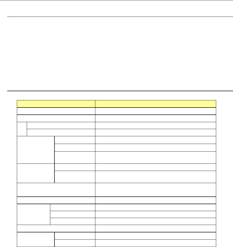
6.8.2. Basic Specifications
Model
DF01
Applicable language Japanese, English
Supply style
Wafer/waffle tray
Wafer supply
Grip ring (for 4-, 5-, 6-, or 8-inch)
Tray supply
Waffle tray (2- or 4-inch)
Component
size
Direct supply
0.3 mm to 10.0 mm Note 1
Shuttle supply 1.0 mm to 10 mm
Allowable
thickness
0.05 mm to 0.725 mm
Target
component to
be used
Wafer Bare chip
Package
component
BGA or CSP, etc. (up to 10 mm)
Supply method
• Face-up supply by shuttle
•
Face-down supply by shuttle (flip chip)
Number of storage pallets 10 pcs.
Grip ring
1 pc./pallet
2-inch waffle tray
8 pcs./pallet (option)
4-inch waffle tray
4 pcs./pallet (option)
Component supply speed 2,400 CPH
Supply
accuracy
XY
±
0.1 mm
θ
±
5
°
Note 1: Separate measures are taken for a size ranging from
10.0 mm to
25.0 mm. For
details, contact JUKI’s sales personnel.