KE-3010A_SPE_EN.pdf - 第29页
- 24 - 4.7.5. Placeme nt enable range on the top and bottom surfaces of PWB *1 : Maximum height s of components that can be placed Ma xim u m Component size S pecification of component height Component diagonal le ss tha…
- 23 -
* For the L-Wide PWB specification, any pin reference option cannot be selected.
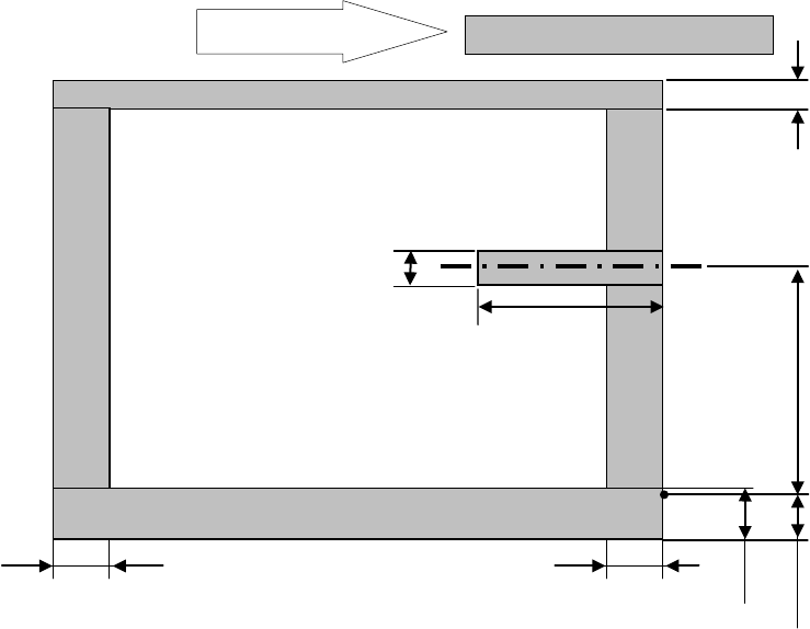
61mm
20mm
22.6mm
0 to 292 mm Moving part
4.5mm
Placement disable range
PWB transport direction
Placement disable range
24.5mm
24.5mm
23mm
L-Wide PWB specification
- 24 -
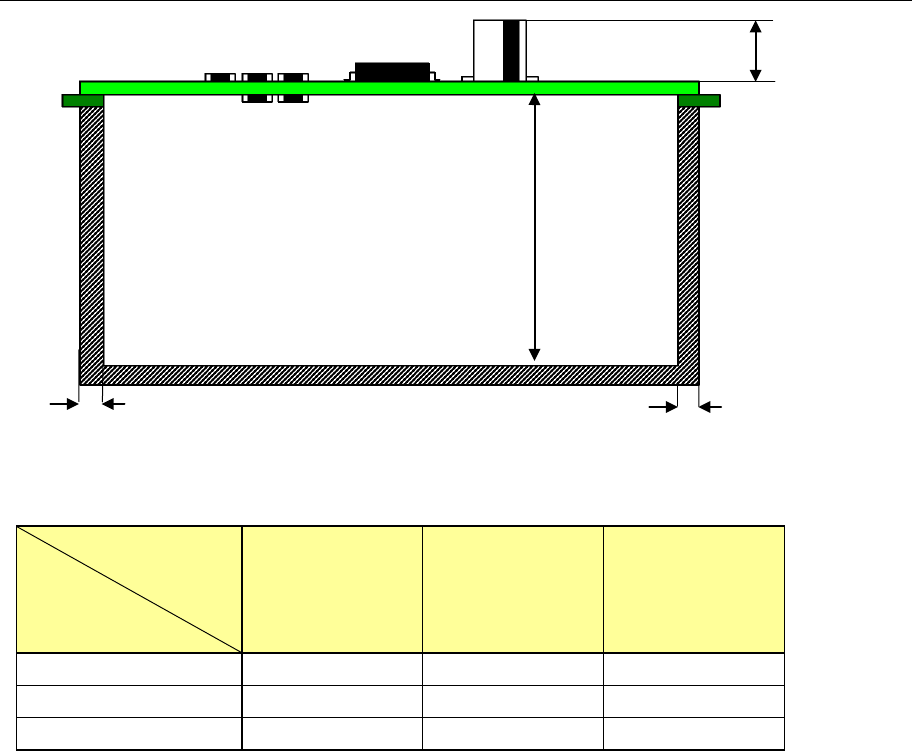
4.7.5. Placement enable range on the top and bottom surfaces of PWB
*1:Maximum heights of components that can be placed
Maximum
Component size
Specification
of component height
Component
diagonal less than
50 mm
Component
diagonal 50 mm or
more to less
than 88 mm
Component
diagonal 88 mm or
more
SC specification 6mm 6mm 6mm
NC specification 12mm 12mm 5mm
HC specification 20mm 20mm 5mm
PWBs clamping method
This is a method to use the PWB top surface as a reference to have both the PWB front
and rear ends each at the fixed and movable sides supported to the transport rails, then,
to clamp the PWBs.
PWB width adjusting methods
* Standard: Manually adjusting method with your hand
* Option: Automatic PWB width adjusting method via a motor
(Minimum board size: 50.0 mm x 50.0 mm)
PWB positioning reference
* Shape reference
* Pine reference (optional)
Maximum *1
SC: 6mm
NC: 12mm
HC: 20mm
EC: 25mm
3mm
3mm
MAX. 40 mm
- 25 -
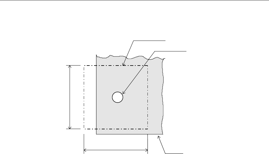
4.7.6. Function correcting the PWB positions
Field of vision for recognizing the PWB reference marks
□6. 3 mm (camera’s field of vision for recognition).
Figure Field of vision for recognizing the PWB reference marks
Window size for recognizing the PWB reference marks
This size can be changed within a maximum of 6.3 mm, subject to securing a clearance
between the recognition mark and its surrounding area.
Kinds of recognition marks and corrective method
- PWB reference mark
Two or three marks are located on a PWB to correct the entire PWB.
When a machine detects two PWB reference marks, it corrects the positioning, angle
and expansion/contraction of the entire PWB. When detecting three PWB reference
marks, it corrects the perpendicularity in the X and Y direction also.
- Component positioning marks
If a component such as an IC (QFP) needs to be placed on a board very precisely, two
or three marks set on a component itself are used to correct each component
placement position.
- Marks used to position the component area
Two marks (their positions can be set as you like) are to be provided to a group of
components placement positions, and they are used to correct each component
placement position in the group.
Note
:
The position is arbitrary, subject to not aligning three (3) reference makes,
if this is the case, on one (1) straight line. (It is recommended that the reference marks
should be made at the four (4) corners of the PWBs.
Field of vision for PWBs recognition
Recognition mark
PWB
6.3mm
6.3mm