KE-3010A_SPE_EN.pdf - 第20页
- 15 - 4.5. A ppl icabl e Component (1) Component size and component hei ght Unit: mm KE - 3010A /3010AC KE - 3020VA /3020VR A MNVC (opti on for KE - 30 10A) Length x width, compo nent dimensio ns Laser rec ognitio n LNC…
- 14 -
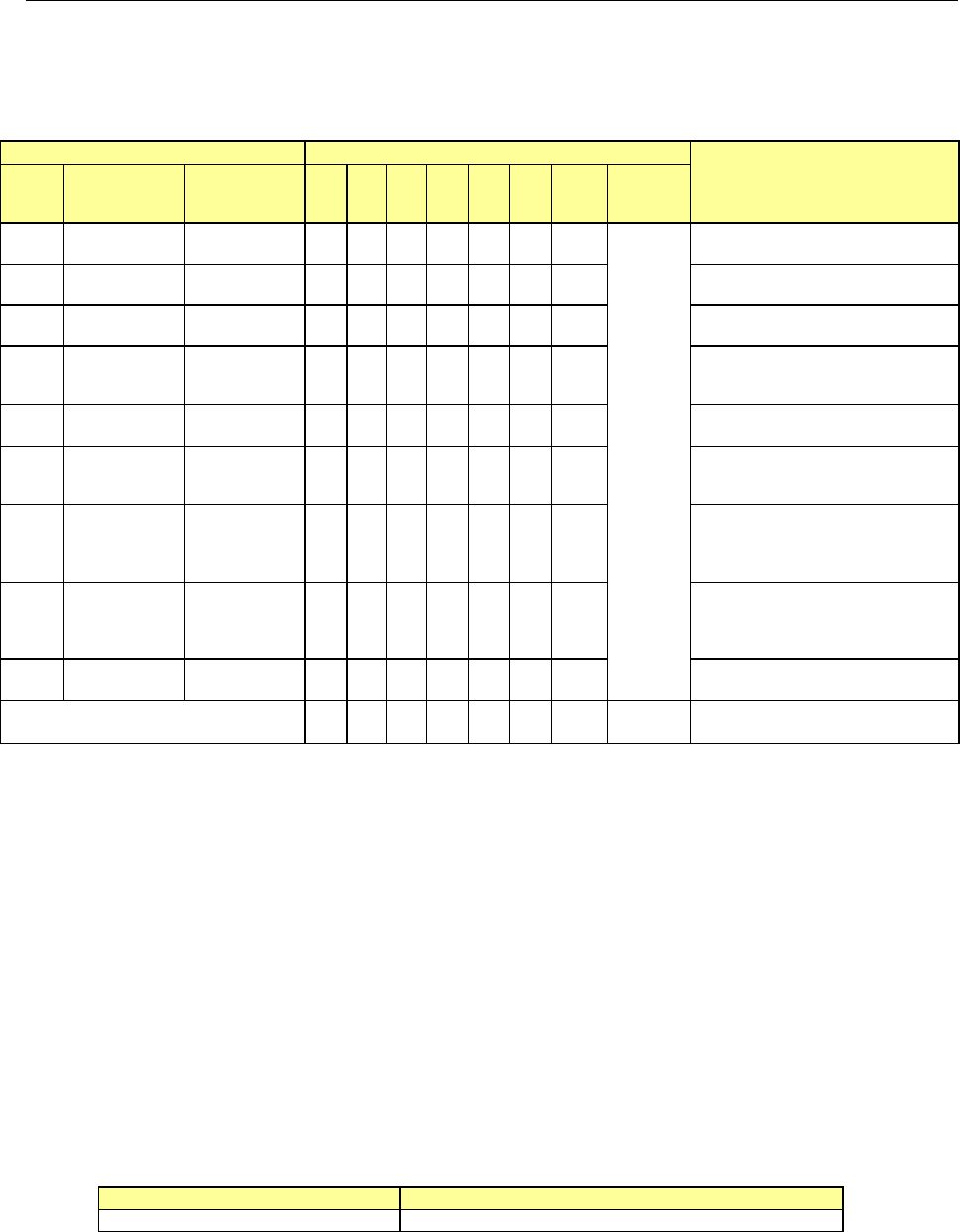
4.4. Nozzles
Various types of nozzles have been designed to increase the reliability of placement of each
type of components as shown in the table below.
You can select one of the nozzle sets shown in Table 1: as the standard nozzles supplied.
Table 1 Nozzles supplied as the standard devices
Nozzle
Nozzle assembly
Applicable components
(reference) and remarks
NO.
Internal
diameter of a
nozzle
External
diameter of a
nozzle
A B D E F G H
Std.
Nozzle
Select
500
2-φ0.4 1.0 x 0.5 − 6 − − − − −
* See
Note 1
1005, 1608, 2012
*See
Note2
SOT (Molding: 1.6 x 0.8)
501
φ0.25 0.7 x 0.4 − − 6 − − −
0603
502
φ0.4 φ0.7 6 − 6 3 − − 3
1005
503
φ0.6 φ1.0 6 − 3 6 3 6 3
1608, 2012, SOT (Molding:
1.6 x 0.8), SOT (Molding: 2.0
x 1.25)
504
φ1.0 φ1.5 − 4 1 3 6 6 3
2012, 3216, SOT23, SOT
(Molding: 2.0 x 1.25)
505
φ1.7 φ3.5 1 2 − 3 3 1 3
Aluminum electrolytic capacitor
(small), tantalum electrolytic
capacitor, trimmer
506
φ3.2 φ5.0 1 1 − 1 3 1 3
Aluminum electrolytic capacitor
(medium),
SOP (narrow type),
SOJ, Connector
507
φ5.0 φ8.5 1 1 − − 1 1 1
Aluminum electrolytic capacitor
(large),
SOP (wide type),
TSOP, QFP, PLCC, Connector
508C
φ8.0 φ9.5 1 1 1 1 1 1 1
QFP, PLCC, BGA
Total number of nozzles 16 15 17 17 17 16 17 15
* Total number of nozzles that can be installed onto an ATC station: 36 pieces (Standard nozzles
34 pieces and up to large-size standard nozzles 2 pieces)
Note 1 As a Std. Nozzle Select, you can select 15 nozzles among those whose number is from 500 to
508C.
However, you have to select a nozzle to be used for calibration of the machine:
・
For laser calibration (one of the nozzle choose from 500, 502 and 503)
・
For image calibration (508C nozzle)
Note 2 Since a theta error may occur due to the shape of the surface of a 2012R component to be picked
up (such as differences of manufactures and/or resistance values), use a No. 504 nozzle if you
have to place 2012R components in the high density (the gap between the adjacent components:
0.3 mm or less).
Limitation on nozzles to be used
(1) Limitation on nozzles used on the LNC60
The LNC60 head cannot be used together with a large nozzle.
(2) Limitation on nozzles used on the IC head side of KE-3020VA
The IC head of KE-3020VA is intended for components of □ 3mm or more. Accordingly,
the following nozzles cannot be used because their nozzle ends are thin. (The IC head
(FMLA) of KE-3020VRA has no limitation for use (except the 509 nozzle)).
Nozzle No. under limitation for use
Standard nozzle
500, 501, 502, 503
Optional nozzles
Other nozzles than the nozzle attached as standard are optional. In addition to the nozzle
dedicated for 0402 (509 nozzle), nozzles matched to different-shape components are prepared.
For details, please ask JUKI sales or dealer.
- 15 -
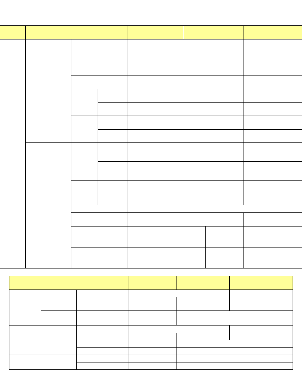
4.5. Applicable Component
(1) Component size and component height
Unit: mm
KE-3010A/3010AC KE-3020VA /3020VRA
MNVC
(option for KE-3010A)
Length x
width,
component
dimensions
Laser recognition
LNC60
*The number of nozzles or
pickup components varies
depending on component
dimensions.
(Note 2) (Note 4) (Note 13)
0.4 x 0.2 to □33.5 or opposite angle length 47 mm -
FMLA
(KE-3020VRA only)
- 1.0×0.5~□33.5 -
Overall vision
recognition
(Note 2) (Note 9)
Standard
camera
(visual field
54 mm)
Reflection -
□3.0~□50.0
(Note 1)
□3.0~□33.5
(Note 1) (Note 14)
Transmission -
□3.0~
□50.0
(Note 1)
□3.0~□6.0
(Note 1)
High-resoluti
on camera
visual field
27 mm)
Reflection -
1.0×0.5~□24.0
(Note 2) (Note 12)
1.0×0.5~□20.0
(Note 2) (Note 12) (Note 15)
Transmission -
□3.0~
□24
(Note 2)
□3.0~□6.0
(Note 2)
Vision sectional
recognition
(Note 2) (Note 6)
(Note 9)
Standard
camera
(visual field
54 mm)
Reflection -
Maximum:
50×150(1 x 3-split)
□
74
(
2 x 2-split
)
Not applicable
Transmission -
Maximum:
50×120(1 x 3-split)
(Note 1) (Note 7)
Not applicable
High-resoluti
on camera
(visual field
27 mm)
Reflection -
24×72(1 x 3-split)
□48(2 x 2-split)
Not applicable
Component
height
The maximum height
varies depending on
the machine
specifications.
SC(T=6mm)
NC(T=12mm)
HC(T=20mm)
EC(T=25mm)
LNC60
0.08 (for 0402) to T
FMLA
(KE-3020VRA only)
- 0.3~T -
VCS overall recognition
(Note 16)
-
CDS
0.4~T
(
Note 5
)
0.08~T
FMLA 0.1~T
VCS sectional recognition
(Note 3) (Note 16)
-
CDS
0.4~T
(Note 5)
Not applicable
FMLA
0.1
~
T
KE-3010A/3010AC KE-3020VA /3020VRA
MNVC
(option for KE-3010A)
Lead pitch
Laser
recognition
LNC60
0.65 or more
-
FMLA
(
KE-3020VRA only
)
- 0.65 or more -
VCS recognition
Standard camera
-
0.38
~
2.54
High accurate camera - 0.20~2.54
Ball pitch
Laser
recognition
LNC60
1.00
~
1.27
-
FMLA
-
1.00
~
1.27
-
VCS recognition
Standard camera - 1.00~3.00
High accurate camera - 0.25~2.00
Ball diameter VCS recognition
Standard camera
-
φ0.4
~
φ1.0
High accurate camera
-
φ0.1
~
φ0.63
- 16 -
Note 1: The minimum size of a component to be recognized with a standard VCS shall be □3.0 mm,
and the size of its mold shall be □1.7 mm or more.
The area to be recognized of the maximum-sized component shall be within the field view of
□52 mm of a standard VCS including the component placement position error and a teaching
error caused when the component is picked up.
For the maximum size of a component that is to be recognized with an MNVC head, the
pick-up XY error shall be 1 mm or less, and the angle error shall be ±3°or less.
When an MNVC head is used for a component whose size exceeds □10 mm, any other
component cannot be assigned to adjacent heads.
When a component is recognized with the back light, and the position 1.3 mm or less far from
the edge of the component is picked up, the shadow of a nozzle may prevent the component
from being recognized stably.
Note 2: The minimum size of a component to be recognized with an optional VCS is 1.0×0.50 mm.
The area to be recognized of the maximum-sized component shall be within the field view of
□25 mm of a standard VCS including the component placement position error and a teaching
error caused when the component is picked up.
For the maximum size of a component to be recognized with an MNVC head, the pick-up XY
error shall be 1 mm or less, and the angle error shall be ±3°or less.
When an MNVC head is used for a component whose size exceeds □10 mm, any other
component cannot be assigned to adjacent heads.
When a component is recognized with the back light, and the position 1.3 mm or less far from
the edge of the component is picked up, the shadow of a nozzle may prevent the component
from being recognized stably. Use a standard VCS as a back light for a large component.
Note 3: When the diagonal line of the external size of a component is 88 mm or more, the height of the
component to be placed on a board is restricted so that it cannot interfere with the LNC.
Note 4: A component whose size is □10 mm is processed with the software as a component whose
diagonal line is 15 mm long (□10.6 mm).
Note 5: The pitch of a general-purpose vision component type of lead component that can be
recognized (such as a multi-pitch connector) is 0.50 to 22.0 mm for a standard VCS or 0.30 to
11.0 mm for an optional high-resolution VCS, which are different from those described in the
table above.
Note 6: The pitch of a general-purpose vision component type of ball component that can be recognized
(such as a composite array) is 1.0 to 22.0 mm for a standard VCS or 0.25 to 11.0 mm for an
optional high-resolution VCS, which are different from those described in the table above.
Note 7: When image of a component is divided to be recognized with using the back light, the minimum
width of the component shall be 17 mm or more. If the width is less than 17 mm, a hole for
moving up/down a nozzle is shot, and the recognition accuracy cannot be guaranteed.
Note 8: When the back light is used to recognize a lead, the lead looks thinner because completely
parallel light is not used.
For some area of the field view, the light illumination from the bottom is used as the back light
with being reflected onto the background plate of the head. Therefore, the lead looks further
narrower when it is positioned in the area lighted with the light from the bottom because the light
is reflected to the lead surface. In some case, the lead cannot be seen at all. As a result,
recognition of a lead with the back light is not guaranteed.
Note 9: The image of a component whose outline is to be recognized cannot be divided into 2×2 for
recognition.
Note 10: Up to 0.4 mm-lead can be recognized with a standard VCS, while up to 0.14-mm lead can be
recognized with an optional high-resolution VCS. Note that if the length of a lead is 0.4 mm or
less, recognition of the lead cannot be guaranteed unless the shape of the lead tip is flat.
Note 11: Neither a lead pitch nor a ball pitch is recognized with laser.
Note 12: To recognize image of a component whose type is not applicable in the list of applicable
component types (such as a resistor chip whose size is from 1.0×0.5 to □3 mm), recognize it as
a general-purpose vision component.