KE-3010A_SPE_EN.pdf - 第27页
- 22 - 4.7.4. Support pin instal lation disable range These dimensions are factory - set ones. The restriction range is added when the reference pin is used. The PWN transport direction is for a cloc kwise flow as show n…
- 21 -
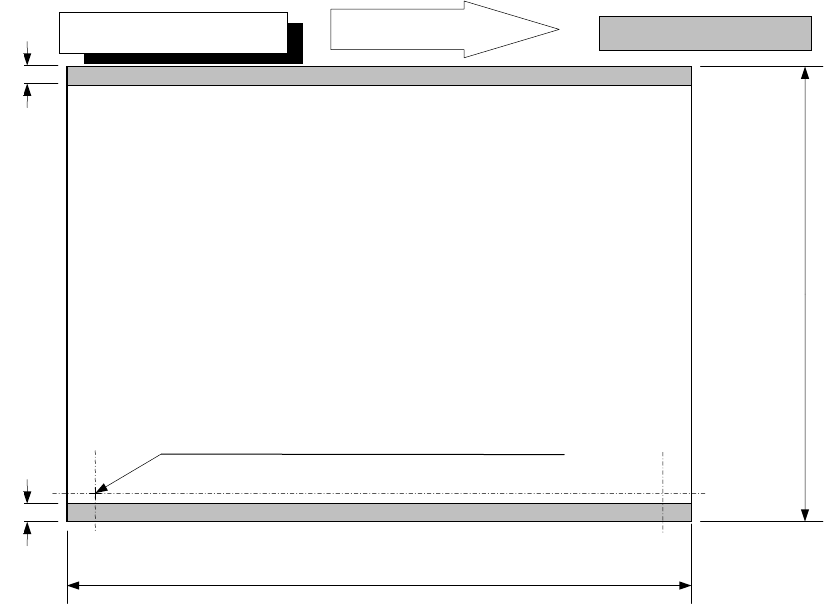
L-Wide PWB specification
PWB transport direction
Placement disable range
3mm
50
~
510mm
3mm
30
~
360mm
50 to 250 mm for the auto PWB width adjusting function
Transport rail fixed side
For L-Wide, the pin standard is not available.
- 22 -
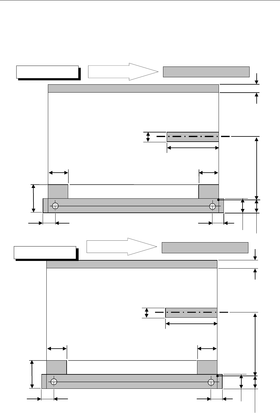
4.7.4. Support pin installation disable range
These dimensions are factory-set ones. The restriction range is added when the
reference pin is used. The PWN transport direction is for a clockwise flow as shown in
the figure. In the case of a flow in the opposite direction, the support pin disable range is
bisymmetrical to the figure.
・PWN bottom drawing
26mm
39.3mm
26.5mm
61mm
26mm
26.5mm
20mm
23mm
22.6mm
0 to 292 mm Moving part
4.5mm
Placement disable range
PWB transport direction
Placement disable range
26mm
39.3mm
26.5mm
61mm
26mm
26.5mm
20mm
23mm
22.6mm
0 to 187 mm Moving part
4.5mm
Placement disable range
PWB transport direction
Placement disable range
M PWB specification
L PWB specification
- 23 -
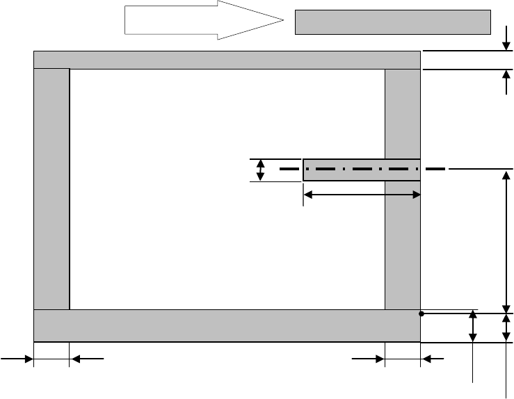
* For the L-Wide PWB specification, any pin reference option cannot be selected.
61mm
20mm
22.6mm
0 to 292 mm Moving part
4.5mm
Placement disable range
PWB transport direction
Placement disable range
24.5mm
24.5mm
23mm
L-Wide PWB specification