Host Computer System.pdf - 第159页
AVK3 HOST COMPUTER SYSTEM 6.2 R Comm ands: R0,R1, R2,R3 D77HEC-55- 020-A0 6.2- 2 Command output exa mple Condition Can be used in opt ional specif ic ation. Vali d i n O NLINE m ode only . Acc u m ul a t ed hours…
AVK3
HOST COMPUTER SYSTEM
6.2 R Commands: R0,R1,R2,R3
D77HEC-55-020-A0
6.2-1
6.2. R Commands: R0,R1,R2,R3
D77HEC-55-020-A0
R (real time) command is to inform the host computer of the changes of conditions during the production
work of AVK3 whenever they occur. This is used as a remote control or to collect production control
information. However, when the host computer is used just for transmission of NC data, if R command is
received, it causes inconveniences. As indicated in ‘1.1.6 Changing Data Transmission Mode’, it is possible
to use the selector switch so that R command does not occur.
6.2.1 Production Quantity Information: R0
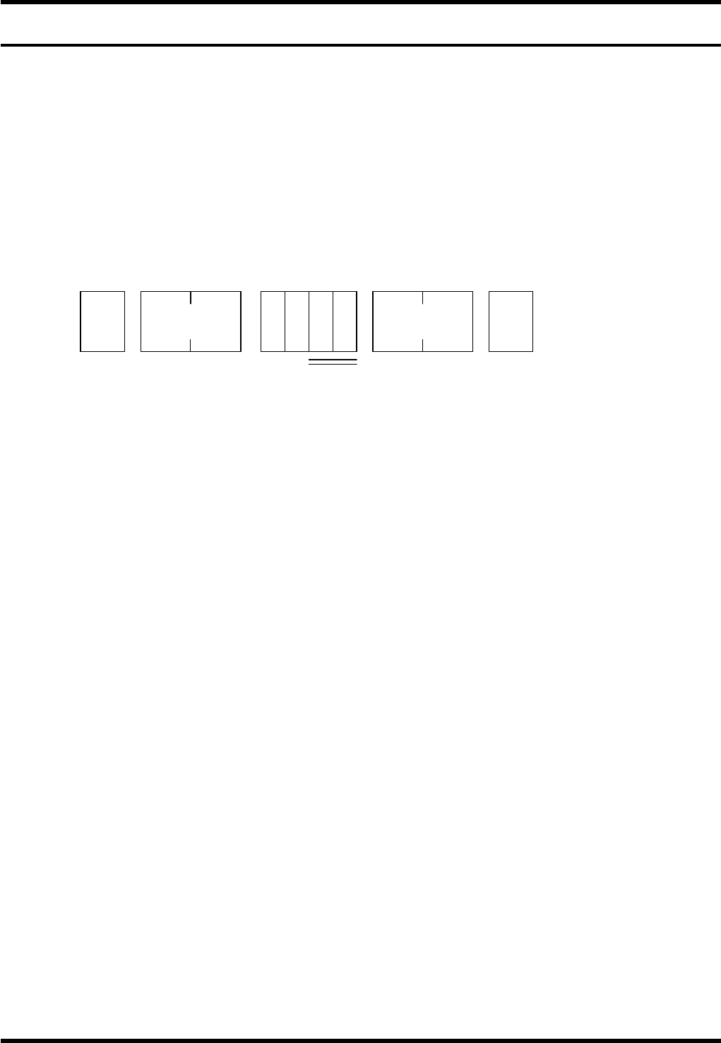
R0 Command is used for totaling the hours worked by AVK3 which started operating by the remote control
command. R0 command has the following 4 functions.
Data details
1.
1. CT
This occurs only when stop mode is in “CONT” and NC program has executed the EOP block.
In case of error, this signal occurs only when restarted in “CONT” mode.
Usually, this is used for counting PCB production.
2. EP
This occurs only when stop mode is in “EOP” or “1BLOCK” and NC program has executed an EOP
block.
Therefore, when an error has occurred at the final dispense block, this signal will not be generated until
operation is by “EOP” or “1BLOCK” key.
This signal can be used to end production. In this case, R0CT is not output.
3. BDGD
In the bad mark sensing corresponding machine, this verifies with the bad mark sensor if the PCB is
capable of being inserted before the actual insertion action.
If it is found to be capable of being inserted, this signal is generated.
4. BDNG
In the bad mark sensing corresponding machine, if the verification results find the PCB as being
incapable (inhibit) of being inserted, this signal is generated.
STX
No. of
characters
R 0
ETX
1 to 4
* *
Check sum
AVK3
HOST COMPUTER SYSTEM
6.2 R Commands: R0,R1,R2,R3
D77HEC-55-020-A0
6.2-2
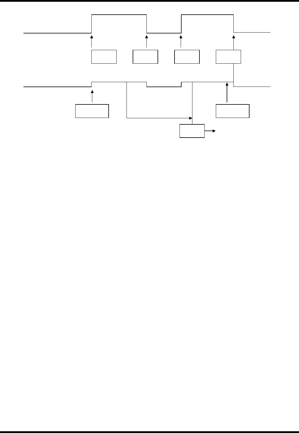
Command output example
Condition
Can be used in optional specification.
Valid in ONLINE mode only.
Accumulated hours
during production
AVK3
(CONT operation)
R1ST
R2E01 R1ST R0EP
C5STCT
R0CT
C5SPEP
EOP stop command
PCB produced count
<EOP>
<EOP>
Specify EOP mode
EOP stop
Insertion error re-start

AVK3
HOST COMPUTER SYSTEM
6.2 R Commands: R0,R1,R2,R3
D77HEC-55-020-A0
6.2-3
6.2.2 Operation mode information: R1
The R1 command is to let the host computer know when an operator or host computer is positively operating
the control switches on the AVK3.
Data details
2.
1. OL or FL
These commands inform the host computer that the control mode of AVK3 is the online (OL) or off-line
(FL). This is generated when mode select switch on the main control panel of AVK3 is switched over,
or immediately after the power is turned ON.
2. ES
When the power is shut down by an emergency stop, R1ES command is outputted by the contact input
of ES switch.
3. ST
This command informs the host computer that AVK3 has started because the START switch on the
main control panel was pressed or a C5ST command was input from the host computer. This is the
signal output when AVK3 has started operation. This signal is also output at the time of restart.
4. SP
This command shows that AVK3 has stopped in conditions other than error.
Actually, it is the normal stopping of 1. Block operation other than at the final print block.
When the NC program switch is “EOP”, this command is not sent and R0EP command is output to
distinguish from stop in EOP stop mode.
5. PS
When a PCB is transferred to the start of the loader rail, the PCB detector 2LS goes ON. When this
switch goes ON (when the PCB is correctly set on the loader rail), this command is output. When
inputting a C5ST start to the AVK3, It is necessary to check that this R1PS command has been
previously input to the host computer.
6. RE
When the “OPERATION RESET” switch on the main control panel has been pressed by the operator
or the C5RE command has been executed by the host computer.
7. PW
In the NC program when G1T4 command is executed, X-Y-Z axes return to origin point and PCB
loading is conducted on X-Y table. At this time, if there is no PCB at the head of the loader rail (that is,
if R1PS command has not occurred prior to it), it is in the PCB arrival waiting condition. In such
conditions, this command occurs.
This signal also occurs when it is impossible to convey away the PCB on the loader rail because the
unloader stocker is full, and PCB loading is impossible.
8. PE
This command shows that the above-mentioned R1PW command condition has been eliminated.
That is, after R1PW has occurred, this command occurs when PCB arrived at head of loader rail, or
when PCB has been discharged to unloader.
9. OC
This is the command informing the host computer that the XY axes started origin return action and
completed the action through inputting C5UP command (PCB sweep out command) from the host
computer.
10. UP
Sweeps out PCB in XY tables through inputting C5UP command from host computer. This is the
command informing the host computer of the C5UP action completion when PCB sweep out was
completed.
STX
No. of
characters
R 1
ETX
1 to 21
* *
Check sum