Host Computer System.pdf - 第63页
AVK3 HOST COMPUTER SYSTEM 3.4 Upl oadi ng I ndiv idual Machine Dat a D77HEC-53- 050-A0 3.4- 2 1) -2 D0AG AnBn Cn 1 2 3 4 No. Data name Max. digit s Out put r an ge Sup- press Fi x Remarks 1 Agi ng comm and 2 × Out …
AVK3
HOST COMPUTER SYSTEM
3.4 Uploading Individual Machine Data
D77HEC-53-050-A0
3.4-1
3.4. Uploading Individual Machine Data
D77HEC-53-050-A0
3.4.1 Uploading Individual Machine Data
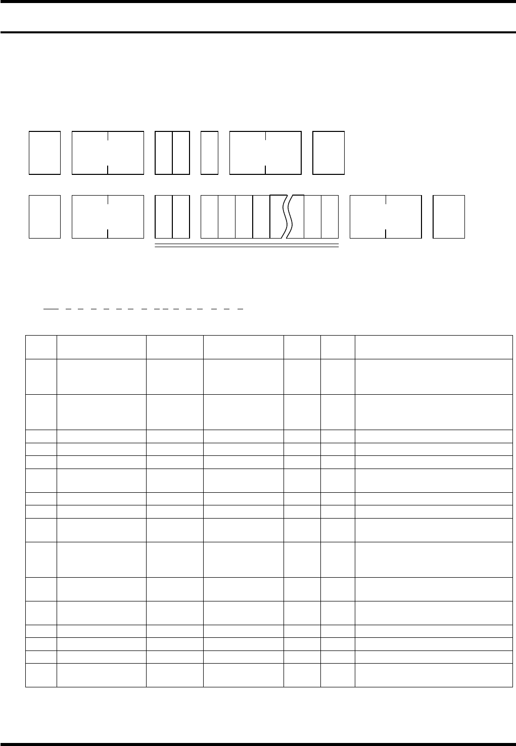
With AVK3, if host computer gives C1 command to AVK3, the AVK3 becomes the receiving mode of the
internal individual machine data and then can send leading block (one block) of individual machine data to
AVK3.
Data details
AVK3 → Host computer
1) -1
D0OCAnBnCnDnEnFnGnHnInJnKnLnMnNnOn
1 2 3 4 5 6 7 8 9 10111213 14 15 16
No. Data name
Max.
digits
Output range
Sup-
press
Fix Remarks
1
Operation
condition
command
2
×
Output command for the
operation condition
2 Z mode 1 0 to 3
×
0 = Priority, 1 = Exchange,
2 = Preparation, 3 =
Connection
3 Priority Z axis 1 0 to 1
×
0 = ZL, 1 = ZR
4 Transfer 1 0 to 2
×
0 = Yes, 1 = No, 2 = Pass
5 Parts prefetch 1 0 to 1
×
0 = Yes, 1 = No
6
In recognition
error
1 0 to 1
×
0 = Continue, 1 = Stop
7 Recovery end 1 0 to 1
×
0 = Continue, 1 = Stop
8 All holes offset 1 0 to 1
×
0 = Yes, 1 = No
9
Optional hole
offset
1 0 to 1
×
0 = Yes, 1 = No
10
PCB
displacement
offset
1 0 to 1
×
0 = Yes, 1 = No
11
PCB inclination
offset
1 0 to 1
×
0 = Yes, 1 = No
12
Modification
offset
1 0 to 1
×
0 = Yes, 1 = No
13
θ axis offset
1 0 to 1
×
0 = Yes, 1 = No
14 Pitch offset 1 0 to 1
×
0 = Yes, 1 = No
15 1st hole offset 1 0 to 1
×
0 = Yes, 1 = No
16
Exchange
connection
1 0 to 1
×
0 = Yes, 1 = No
STX
C 1 G
No. of
characters
ETX
Check sum
STX
D 0
No. of
characters
ETX Check sum
1) -1 to 37

AVK3
HOST COMPUTER SYSTEM
3.4 Uploading Individual Machine Data
D77HEC-53-050-A0
3.4-2
1) -2
D0AGAnBnCn
1 2 3 4
No. Data name
Max.
digits
Output range
Sup-
press
Fix Remarks
1 Aging command 2
×
Output command for the aging
2 Aging mode 1 0 to 1
×
Aging mode
0 = Valid, 1 = Invalid
3 Anvil short 1 0 to 1
×
Anvil short
0 = Valid, 1 = Invalid
4 Parts detection 1 0 to 1
×
Parts detection
0 = Valid, 1 = Invalid
1) -3
D0PRAnBn
1 2 3
No. Data name
Max.
digits
Output range
Sup-
press
Fix Remarks
1
Parts remove
support
command
2
×
Output command for the parts
remove support
2
Parts remove
support
1 0 to 1
×
Parts remove support
0 = Valid, 1 = Invalid
3 Support position 1 0 to 1
×
Support position
0 = Bottom of camera,
1 = Table origin
1) -4
D0ECAnBnn
1 2 3
No. Data name
Max.
digits
Input range
Sup-
press
Fix Remarks
1
Parts exhaust
retry command
2
×
Command for the parts
exhaust retry
2 Retry setting 1 0 to 1
×
Retry setting
0 = Invalid, 1 = Valid
3 Retry count 2 0 to 99
×
Retry count
1) -5
D0ER Fn
1 2
No. Data name
Max.
digits
Input range
Sup-
press
Fix Remarks
1
EOP recovery
command
2
×
Command for the EOP
recovery
2
EOP recovery
setting
1 0 to 1
×
EOP recovery
0 = Invalid, 1 = Valid

AVK3
HOST COMPUTER SYSTEM
3.4 Uploading Individual Machine Data
D77HEC-53-050-A0
3.4-3
1) -6
D0RSFn
1 2
No. Data name
Max.
digits
Input range
Sup-
press
Fix Remarks
1
Insertion error
non-clear
command
2
×
Command for the insertion
error non-clearing
2
Insertion error
non-clear
setting
1 0 to 1
×
Insertion error non-clear
setting
0 = Can be cleared with
“RESET”.
1 = Cannot be cleared with
“RESET”.
1) -7
D0RPnn
1 2
No. Data name
Max.
digits
Output range
Sup-
press
Fix Remarks
1
Command by
production count
2
×
Output command for the set
data by production count
2 Count 2 0 to 99
×
Setting by count
0 = Only once at the beginning
of model changeover
1 = Every time
2 = Every two boards
1) -8
D0ARnRnn
1 2 3
No. Data name
Max.
digits
Input range
Sup-
press
Fix Remarks
1
Command by
production count
2
×
Output command for the
automatic recovery
2 Count 1 0 to 1
×
Recovery setting
0 = Valid, 1 = Invalid
3
Command by
production count
2 0 to 99
×
Recovery count
1) -9
D0DTDn
1 2
No. Data name
Max.
digits
Input range
Sup-
press
Fix Remarks
1
Data type
command
2
×
Output command for the data
type
2 Data type 1 0 to 1
×
0 = ABS, 1 = INC