Host Computer System.pdf - 第61页
AVK3 HOST COMPUTER SYSTEM 3.3 Upl oadi ng P. C.B. Data D77HEC-53- 030-A1 3.3- 2 Protocol Condition Vali d i n O NLINE m ode only . If a program which does not ex ist in the mem ory is specifi ed, ‘A3’ is ret urne…
AVK3
HOST COMPUTER SYSTEM
3.3 Uploading P.C.B. Data
D77HEC-53-030-A1
3.3-1
3.3. Uploading P.C.B. Data
D77HEC-53-030-A1
3.3.1 Uploading P.C.B. Data
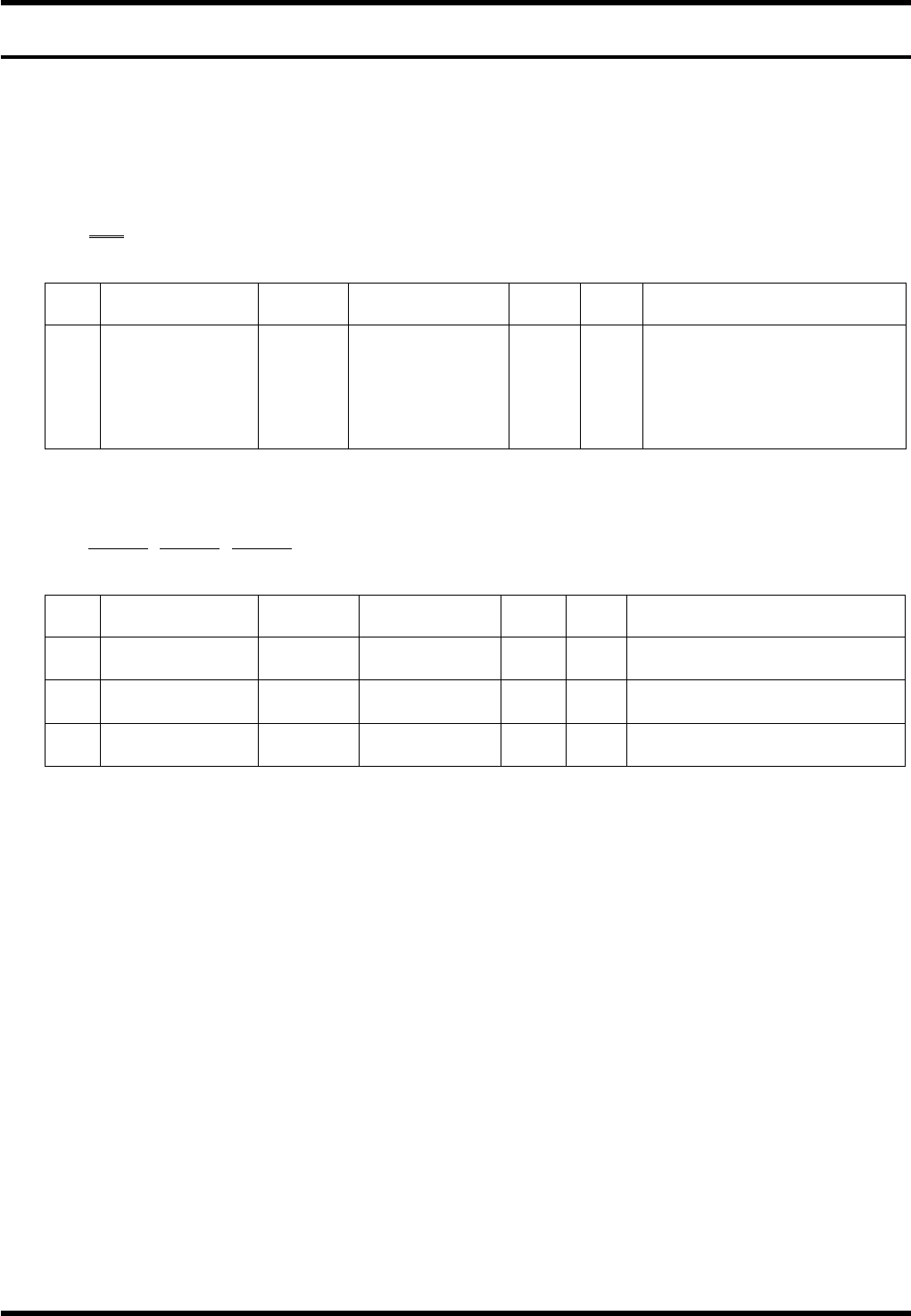
Data details
1) -1
C1C∗ - ∗
1
No. Data name
Max.
digits
Input range
Sup-
press
Vari-
able
Remarks
1 Program name 15
‘0’ to ‘9’
‘A’ to ‘Z’
Special character
×
If other than the valid
character, ‘A4E01’ is
returned.
If the name does not exist in
the memory, ‘A3’ is
returned.
1) -2
D0XnnnnnnYnnnnnnHnnnnnn
1 2 3
No. Data name
Max.
digits
Input range
Sup-
press
Vari-
able
Remarks
1
PCB dimension
X
6 0 to 999999
×
Only + direction
µm
2
PCB dimension
Y
6 0 to 999999
×
Only + direction
µm
3
Reference hole
pitch
6 0 to 999999
×
Only + direction
µm
AVK3
HOST COMPUTER SYSTEM
3.3 Uploading P.C.B. Data
D77HEC-53-030-A1
3.3-2
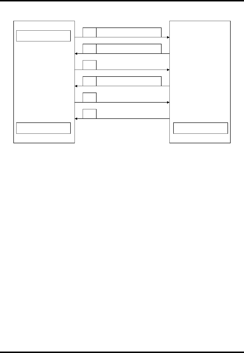
Protocol
Condition
Valid in ONLINE mode only.
If a program which does not exist in the memory is specified, ‘A3’ is returned.
After receiving ‘A2’ from HOST, the processing ends.
Start of upload
Host computer
Sends out PCB data.
AVK3
D 0 PCB data
A 0
C1C Program name
D 0
∗
Requests next data.
A 0
Sends out EOP data.
A 2
End of transmission
End of reception
AVK3
HOST COMPUTER SYSTEM
3.4 Uploading Individual Machine Data
D77HEC-53-050-A0
3.4-1
3.4. Uploading Individual Machine Data
D77HEC-53-050-A0
3.4.1 Uploading Individual Machine Data
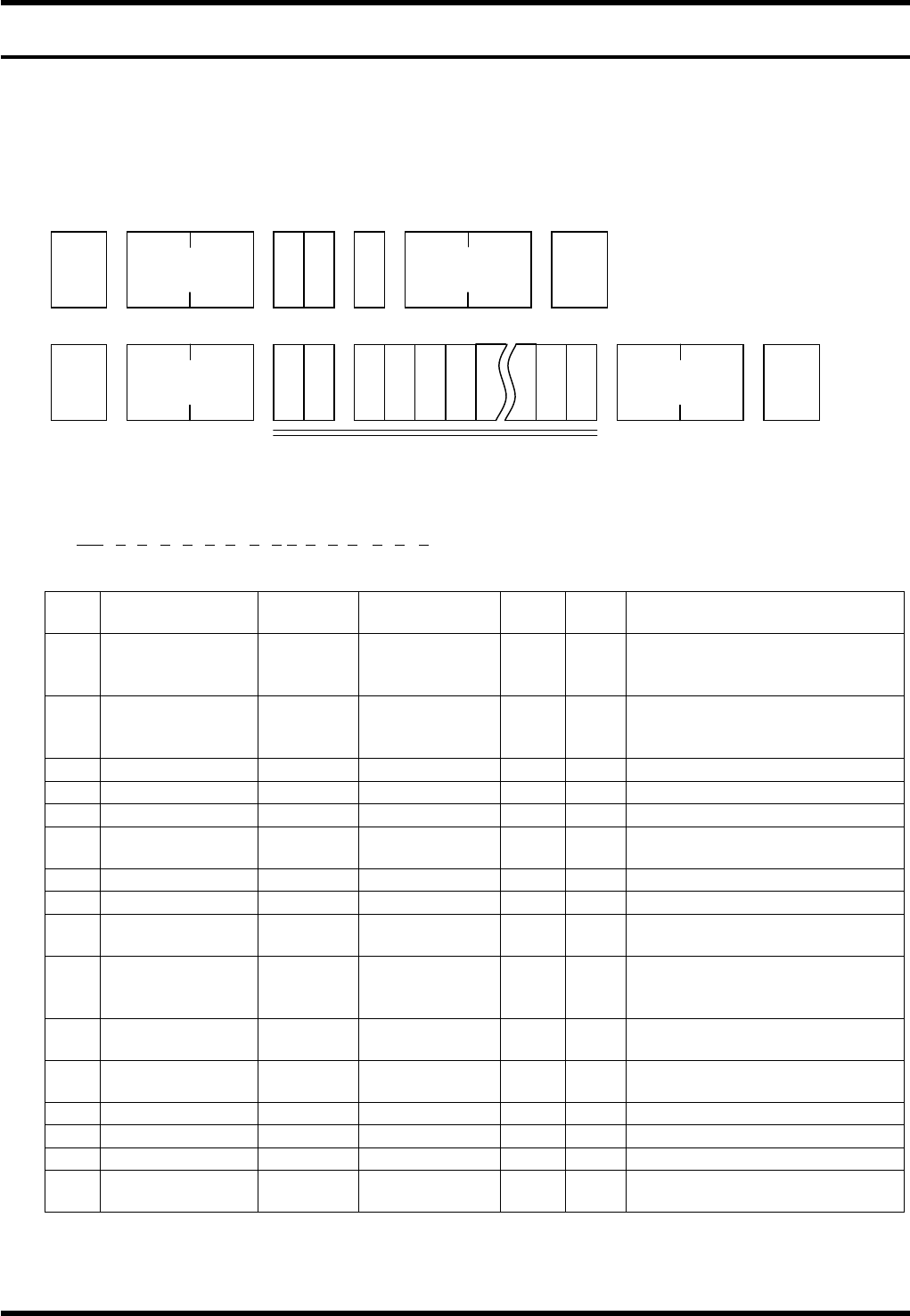
With AVK3, if host computer gives C1 command to AVK3, the AVK3 becomes the receiving mode of the
internal individual machine data and then can send leading block (one block) of individual machine data to
AVK3.
Data details
AVK3 → Host computer
1) -1
D0OCAnBnCnDnEnFnGnHnInJnKnLnMnNnOn
1 2 3 4 5 6 7 8 9 10111213 14 15 16
No. Data name
Max.
digits
Output range
Sup-
press
Fix Remarks
1
Operation
condition
command
2
×
Output command for the
operation condition
2 Z mode 1 0 to 3
×
0 = Priority, 1 = Exchange,
2 = Preparation, 3 =
Connection
3 Priority Z axis 1 0 to 1
×
0 = ZL, 1 = ZR
4 Transfer 1 0 to 2
×
0 = Yes, 1 = No, 2 = Pass
5 Parts prefetch 1 0 to 1
×
0 = Yes, 1 = No
6
In recognition
error
1 0 to 1
×
0 = Continue, 1 = Stop
7 Recovery end 1 0 to 1
×
0 = Continue, 1 = Stop
8 All holes offset 1 0 to 1
×
0 = Yes, 1 = No
9
Optional hole
offset
1 0 to 1
×
0 = Yes, 1 = No
10
PCB
displacement
offset
1 0 to 1
×
0 = Yes, 1 = No
11
PCB inclination
offset
1 0 to 1
×
0 = Yes, 1 = No
12
Modification
offset
1 0 to 1
×
0 = Yes, 1 = No
13
θ axis offset
1 0 to 1
×
0 = Yes, 1 = No
14 Pitch offset 1 0 to 1
×
0 = Yes, 1 = No
15 1st hole offset 1 0 to 1
×
0 = Yes, 1 = No
16
Exchange
connection
1 0 to 1
×
0 = Yes, 1 = No
STX
C 1 G
No. of
characters
ETX
Check sum
STX
D 0
No. of
characters
ETX Check sum
1) -1 to 37