EdisonStandardOwnersManual-RevA-20170818B.pdf - 第140页
M AINTENANCE Edison Printer User Manual (Part Number 1023838) 140 Rev. A Copyright © 2017 ITW EAE All rights reserved. No part of the contents of thi s manual may be reproduced, copied or transmitted in any form or by an…

Edison Printer User Manual (Part Number 1023838) MAINTENANCE
Rev. A 139
Copyright © 2017 ITW EAE
All rights reserved. No part of the contents of this manual may be reproduced, copied or transmitted in any form or by any
means including graphic, electronic, or mechanical methods or photocopying, recording, or information storage and
retrieval systems without the written permission of ITW EAE, unless for purchaser's personal use.
NOTE: The E-Stop switch is intended for emergency use only. Use the white Power Off switch
for normal printer shutdown.
6.2.4.2. Verify Motion Power Off Operator Switch Functionality—Monthly
Introduction
Verify white Power Off operator switch functionality monthly routine (Figure 138).
Estimated Completion Time
Less than 5 minutes
Procedure
Bring the printer to a fully initialized condition.
Load a process program, then:
o Push the white Motion Power Off button to ensure the system shuts down the air and
motion control elements of the printer.
o The button is a momentary contact type and should return to the normal position.
Open hood.
Examine the back side of the switch:
o Verify wire connections to the switch are secure.
o Verify the operator block is properly fastened.
NOTE: The white Motion Power Off button does not illuminate at any time.
6.2.4.3. Verify Power On Operator Switch Functionality—Monthly
Introduction
Verify green Power On (24V ON) operator switch functionality monthly routine (Figure 138).
Estimated Completion Time
Less than 5 minutes
Procedure
Start from a complete printer Power Off condition.
Turn printer main breaker ON.
Push the green 24V ON (Power On) button to start the power control module.
o Note that the green light on the 24V ON switch comes on and stays ON, ensuring 24
VDC supply is functional.
o The switch is a momentary contact type and should return to the normal position.
Open hood.
Examine the back side of the switch:
o Verify wire connections to the switch are secure.
o Verify the operator block is properly fastened.
NOTE:
MAINTENANCE Edison Printer User Manual (Part Number 1023838)
140 Rev. A
Copyright © 2017 ITW EAE
All rights reserved. No part of the contents of this manual may be reproduced, copied or transmitted in any form or by any
means including graphic, electronic, or mechanical methods or photocopying, recording, or information storage and
retrieval systems without the written permission of ITW EAE, unless for purchaser's personal use.
If the light comes ON but the goes OFF, check the circuitry associated with the system
power. Reference the electrical drawing.
If the light does not come ON but the printer power is ON, replace the switch because the
switch lamp is defective.
6.2.5. Verify Cover Interlock Active/Bypass Key Switch Operator Switch
Functionality—Monthly
Figure 139. Check Cover Interlock Bypass.
Introduction
Verify Cover Interlock Active / Bypass Key switch operator switch functionality
monthly routine.
Estimated Completion Time
Less than 5 minutes
Procedure
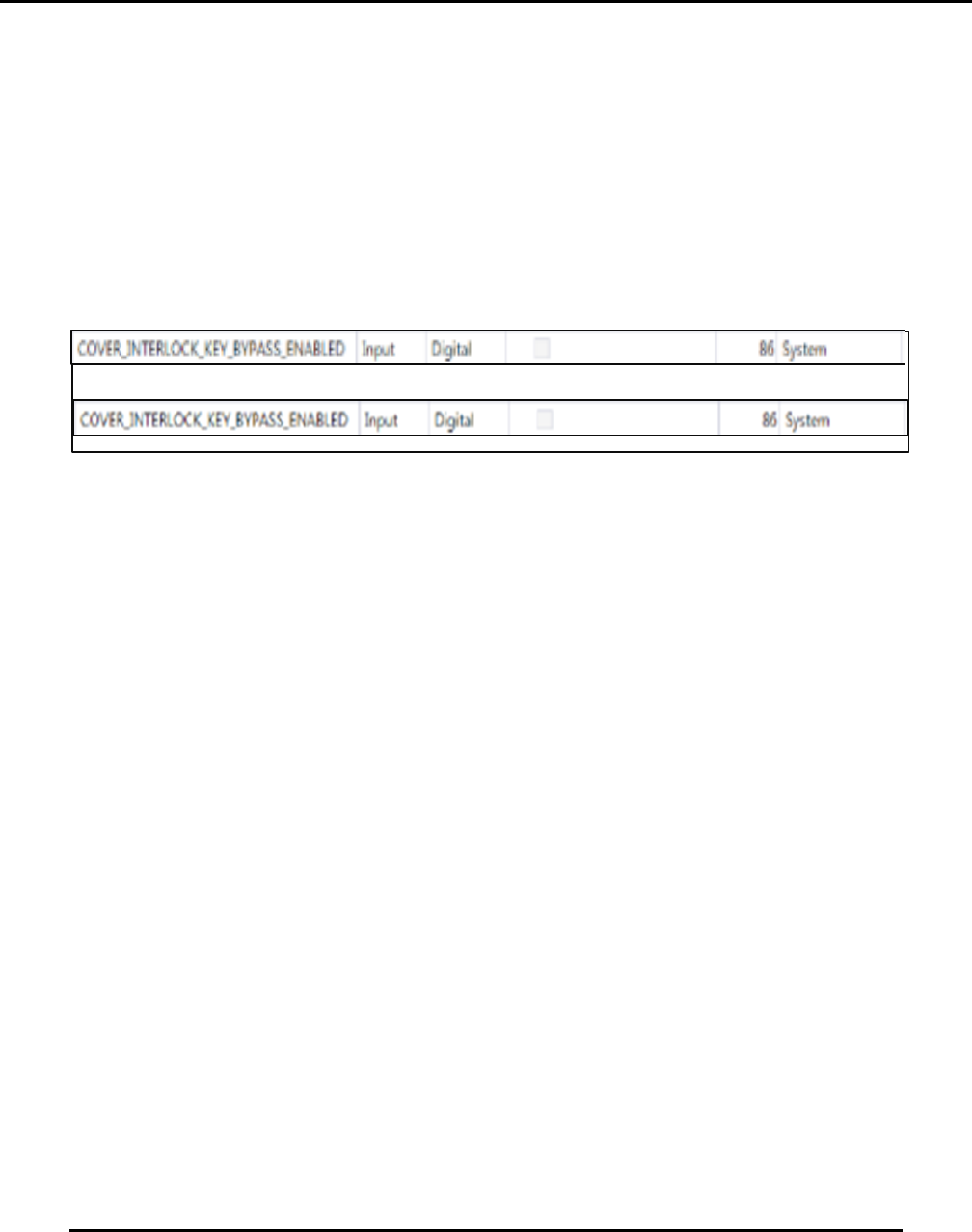
Navigate to View > Diagnostics > IO View.
Click on System Group in Groups.
Turn the Cover Interlock key from Active to Bypass (Figure 138).
o The checkbox associated with COVER_INTERLOCK_KEY_BYPASS_ ENABLED
will go from unchecked to checked (Figure 139).
Open hood.
Examine the back side of the switch:
o Verify wire connections to the switch are secure.
o Verify the operator block is properly fastened.
NOTE:
The Cover Interlock key is for used by properly trained technical personnel for maintenance
purposes such as calibrations.
After verifying Cover Interlock key functionality, remove and secure the key. Do not leave
the Cover Interlock in the printer.
X
Edison Printer User Manual (Part Number 1023838) MAINTENANCE
Rev. A 141
Copyright © 2017 ITW EAE
All rights reserved. No part of the contents of this manual may be reproduced, copied or transmitted in any form or by any
means including graphic, electronic, or mechanical methods or photocopying, recording, or information storage and
retrieval systems without the written permission of ITW EAE, unless for purchaser's personal use.
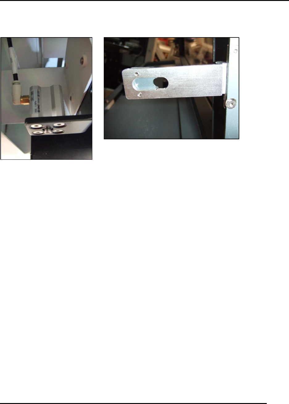
6.2.6. Verify Hood Lock Cylinder Functionality—Monthly
Figure 140. Hood lock adjustments.
Introduction
Verify hood lock cylinder functionality.
Estimated Completion Time
Less than 5 minutes
Procedure
Start from printer power ON.
Set in Initialize Controllers Only condition.
Close hood.
Observe icon at the top of the display change from a subdued state to a yellow open lock
state.
o Click on the icon to lock the hood.
o The lock icon should go green.
Attempt to open the hood manually by lifting and by vigorous shaking from left to right.
o If the hood can be opened, adjust the pneumatic cylinder on the left side (Figure 140).
o If the hood cannot be opened but the printer shuts down with a Hood State Changed
Unexpectedly fault, adjust the S1 safety switch.