EdisonStandardOwnersManual-RevA-20170818B.pdf - 第47页
Edison Printer User Manual (Part Number 1023838) I NSTALLATION AND I NITIA L S T A RT - U P Rev. A 47 Copyright © 2017 ITW EAE All rights reserved. No part of the contents of this manual may be reproduced, copi ed or tra…
INSTALLATION AND INITIAL START-UP Edison Printer User Manual (Part Number 1023838)
46 Rev. A
Copyright © 2017 ITW EAE
All rights reserved. No part of the contents of this manual may be reproduced, copied or transmitted in any form or by any
means including graphic, electronic, or mechanical methods or photocopying, recording, or information storage and
retrieval systems without the written permission of ITW EAE, unless for purchaser's personal use.
3.2. Unpacking Instructions
Unpack the Edison printer in an area suitable to safely remove crating and packing materials.
After unpacking, use a forklift to skid the printer into place in final operating area.
Attention
All retaining screws (2.5 in/ 63.5mm Phillips Head) are located within 1
in/ 25.4mm of the crate edges.
Attention—Lifting Edison Printer
ITW EAE recommends extended forklift blades of 60 in to 72 in
(152.4cm to 182.8cm) in length to ensure proper weight distribution
when lifting the printer from the skid.
Ensure forklift blades have a total width/span of 36 in (91.44cm).
Ensure the forklift blades are placed within the area designated by
the left and right forklift blade labels, located on the sides of the
printer.
Ensure the forklift is capable of lifting 3000 lbs. (1360.78 kg)
Attention
Do not permit personnel beneath forklift blades or printer at any time.
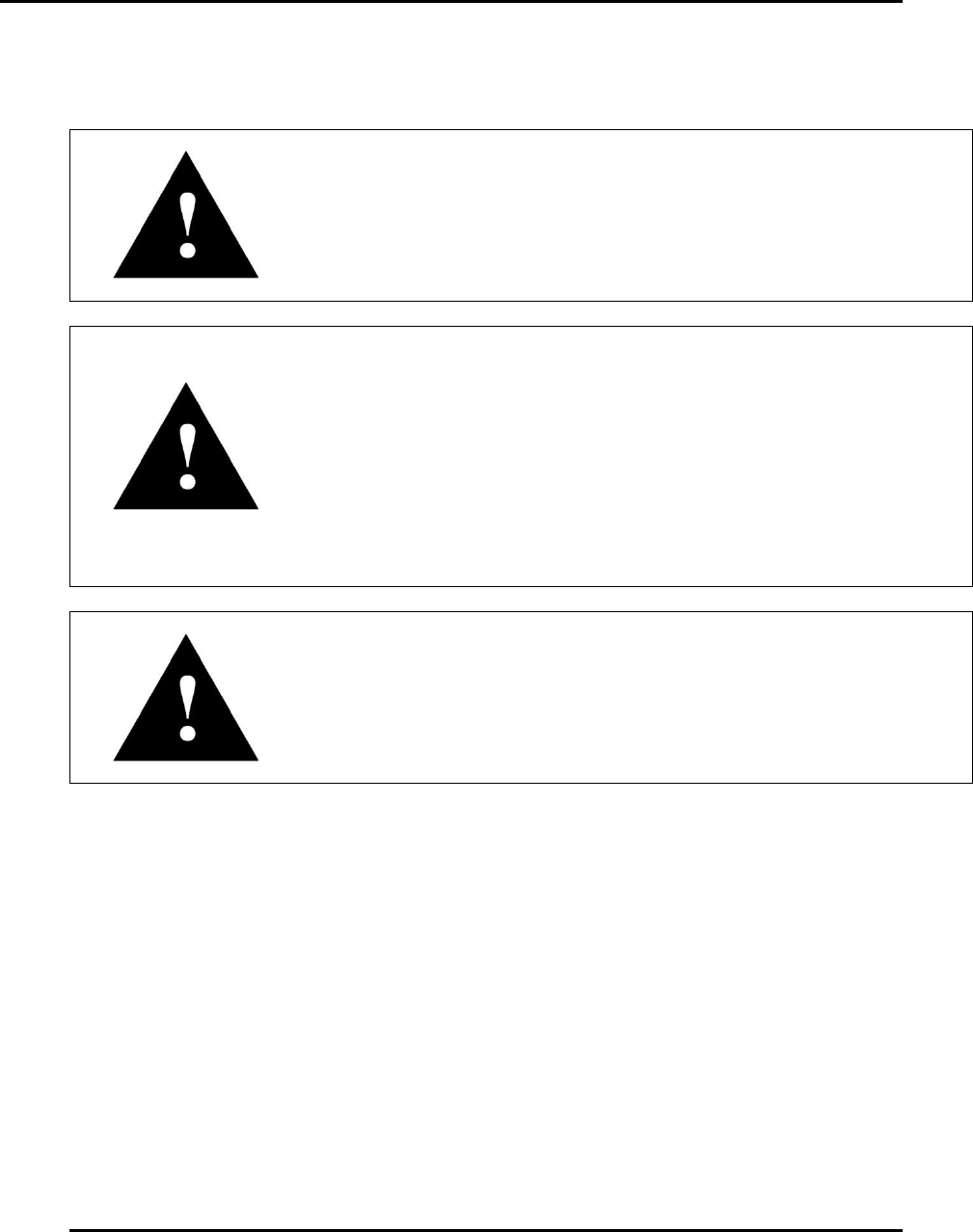
3.2.1. Remove crating.
1. Remove the screws securing the top of the crate to the front, rear and two side panels (Figure
18).
2. Remove the crate top and set aside.
a. Ensure the crate top does not fall into the crate and damage the printer.
3. Remove the screws securing one side panel to the crate.
4. Remove the side panel to expose the printer.
5. Repeat the above for the remaining side panels.
Edison Printer User Manual (Part Number 1023838) INSTALLATION AND INITIAL START-UP
Rev. A 47
Copyright © 2017 ITW EAE
All rights reserved. No part of the contents of this manual may be reproduced, copied or transmitted in any form or by any
means including graphic, electronic, or mechanical methods or photocopying, recording, or information storage and
retrieval systems without the written permission of ITW EAE, unless for purchaser's personal use.
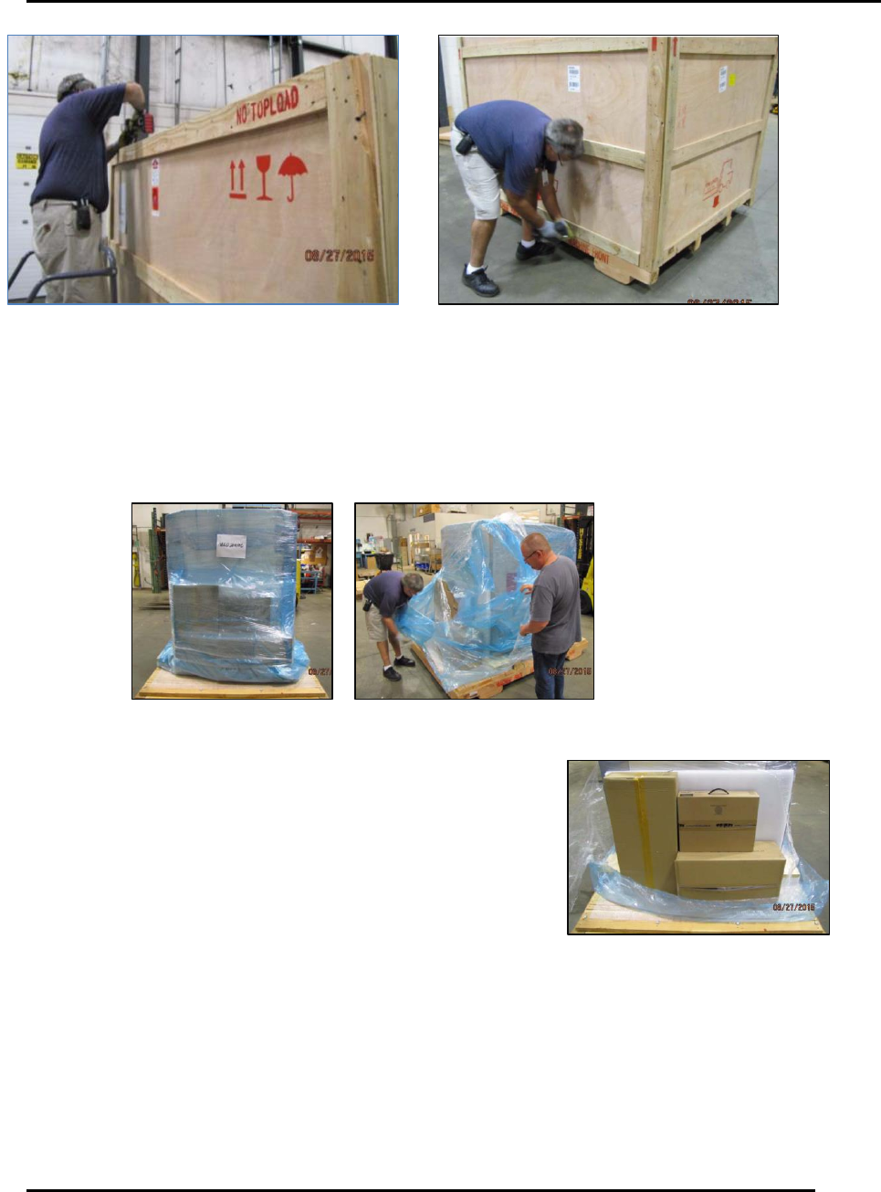
3.2.2. Remove packing material and shipping boxes
1. If present, carefully remove blue vacuum bag from the printer (Figure 19).
2. Carefully remove shrink wrap from the printer.
Figure 19. Expose and remove printer from packing materials.
3. Locate the shipping boxes packed with the printer and move
them away from the work area (Figure 20).
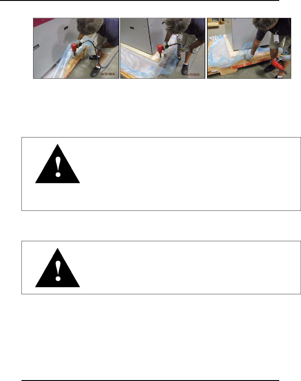
4. Remove bottom of crating (Figure 21).
a. Remove the mounting hardware securing the two support timbers running from the left
side of the skid to the right side.
b. Remove the mounting hardware securing the foam isolators to the skid using a ¾ in.
socket.
c. Slide the two support timbers out from under the printer.
Figure 18. Remove crating.
Figure 20. Locate and move shipping
boxes from work area.
INSTALLATION AND INITIAL START-UP Edison Printer User Manual (Part Number 1023838)
48 Rev. A
Copyright © 2017 ITW EAE
All rights reserved. No part of the contents of this manual may be reproduced, copied or transmitted in any form or by any
means including graphic, electronic, or mechanical methods or photocopying, recording, or information storage and
retrieval systems without the written permission of ITW EAE, unless for purchaser's personal use.
Figure 21. Remove crating bottom, isolators and supports.
3.2.3. Lift Edison Printer
1. Position forklift blades and lift to remove skid (Figure 22).
Attention—Lifting Edison Printer
ITW EAE recommends extended forklift blades of 60 in to 72 in
(152.4cm to 182.8cm) in length to ensure proper weight distribution
when lifting the printer from the skid.
Ensure forklift blades have a total width/span of 36 in (91.44cm).
Ensure the forklift blades are placed within the area designated by
the left and right forklift blade labels, located on the sides of the
printer.
Ensure the forklift is capable of lifting 3000 lbs. (1360.78 kg)
2. Position forklift blades under the printer base and within the area designated by the left and
right forklift labels located on the sides of the printer (Figure 22).
Attention
Ensure forklift blades extend fully across the printer base and do not
pinch any loose pneumatic or electrical lines under the printer.
3. Lift the printer off the skid high and enough to remove the isolators from the bottom of the
printer.
4. Remove the skid from beneath the printer.
5. Remove the foam plugs from the bottom of the isolators to expose the hardware securing the
isolators to the bottom of the printer.
6. Remove the isolators from the printer with a 30mm socket.