00191297-02.pdf - 第175页
User Manual S-23 HM 6 Vision functions Software Vers ion SR.405.xx 05/99 Iss ue 6.2 PCB vision s ystem 173 – t rigger a nd flash s ignals (10-pin r ibbon ca ble conne ctor ) and status di splay L EDs for 6 – the CPU (CFG…
6 Vision functions User Manual S-23 HM
6.2 PCB vision system Software Version SR.405.xx 05/99 Issue
172
6.2 PCB vision system
The PCB vision system records the precise position of the PCB by measuring fiducials, and cal-
culates the offset in the x and y directions, the angle of rotation relative to the PCB transport di-
rection and the shear acting on the PCB. Reject fiducials (ink spots) are also recorded and
analyzed by the PCB vision system. 6
6.2.1 System description
The PCB vision system for detecting the position of PCBs consists of the optical PCB position de-
tection system and the vision analysis unit. 6
Optical PCB position detection system 6
Each gantry has a separate PCB position detection system (see Fig. 6.1 - 3 on page 168). 6
Vision analysis unit 6
The control unit of each placement system contains one analysis unit for detecting the position of
PCBs and components (see Fig. 6.1 - 4 on page 170). 6
A CCD camera (SONY XC75) with integral mapping and illumination lens forms the optical PCB
position detection system. The field of view of the PCB module is 5.7 mm x 5.7 mm. The size and
position of the search field can be programmed as required within the fields of view. The mapping
lens is a special measuring lens which corrects most errors caused by the curvature of the PCB.
The illumination is switched on only while fiducials are being recorded. 6
The vision analysis unit (MVS) is a single-board system conforming to VME standards. The hard-
ware consists of 6
– the MVS motherboard with vision processor and interface connections
– and the MVS camera interface for up to four CCD cameras.
MVS motherboard with vision processor and interface connections 6
The two VME bus connections are located on the back of the VME module. 6
The front panel of the VME module contains connectors for 6
– the monitor (VGA mode, 15-pin SUBD connector)
– the high-speed interface (HS
3
L), 9-pin SUBD connector
– up to 4 camera inputs (2 x 15-pin SUBD connector)
– two serial interfaces (RS232 for COM1 with a 25-pin SUBD connector and COM2 with a
9-pin SUBD connector)
User Manual S-23 HM 6 Vision functions
Software Version SR.405.xx 05/99 Issue 6.2 PCB vision system
173
– trigger and flash signals (10-pin ribbon cable connector)
and status display LEDs for 6
– the CPU (CFG)
– the vision processor (ACA)
– the camera input (BCA)
– the screen display (DISP)
6.2.2 Technical Data
Camera model: SONY XC75 6
Number of pixels: Camera 768 (H) x 494 (V), Image 640 (H) x 484 (V) 6
Field of view: 5.7 mm x 5.7 mm 6
Illumination method: Incident light method (activated during measurement) 6
Image processing: Correlation principle, gray scale system 6
Processor cycle time: < 200 msec 6
Screen: RGB monitor (VGA mode) 640 x 484 pixels in the station computer6
Fiducials: Library memory for up to 255 fiducial definitions 6
6.2.3 Description of Functions
Before placement the location, skew and shear of the board is determined by the PCB vision sys-
tem using the position of the fiducials. Deviations from the setpoint values are then included in the
calculation of the placement positions of the components as corrections. 6
A board must have at least 2 fiducials if the system is to be able to detect deviations in the board
position and the skew of the board. The presence of 3 fiducials will furnish additional information
concerning shear or stretching of the board or of the board layout. 6
6.2.4 Sequence of Functions
Before a fiducial can be used for board recognition it must first be ’taught’ to the machine. In other
words, the fiducial structure parameters must have been saved in the PCB vision system for that
pattern. 6
The fiducial structure can be taught using the PCB vision camera mounted on the gantry and the
vision program. The vision analysis unit determines the significant fiducial structure parameters
using digital image processing methods. 6
6 Vision functions User Manual S-23 HM
6.2 PCB vision system Software Version SR.405.xx 05/99 Issue
174
Measurement takes place in two stages: 6
– 2-D pattern search (2-dimensional process) in the coarse grid and provisional determina-
tion of the fiducial coordinates
– 1-D pattern search (1-dimensional process) for a precise determination of the position of
the fiducials.
With the 2-D pattern search process the template window is divided into moxel areas. Moxels
(mosaic pixels) are pixel fields containing for example 16 x 16, 8 x 8 pixels and so on. The lower
the pixel count per moxel the higher the resolution and the lower the search speed. 6
6
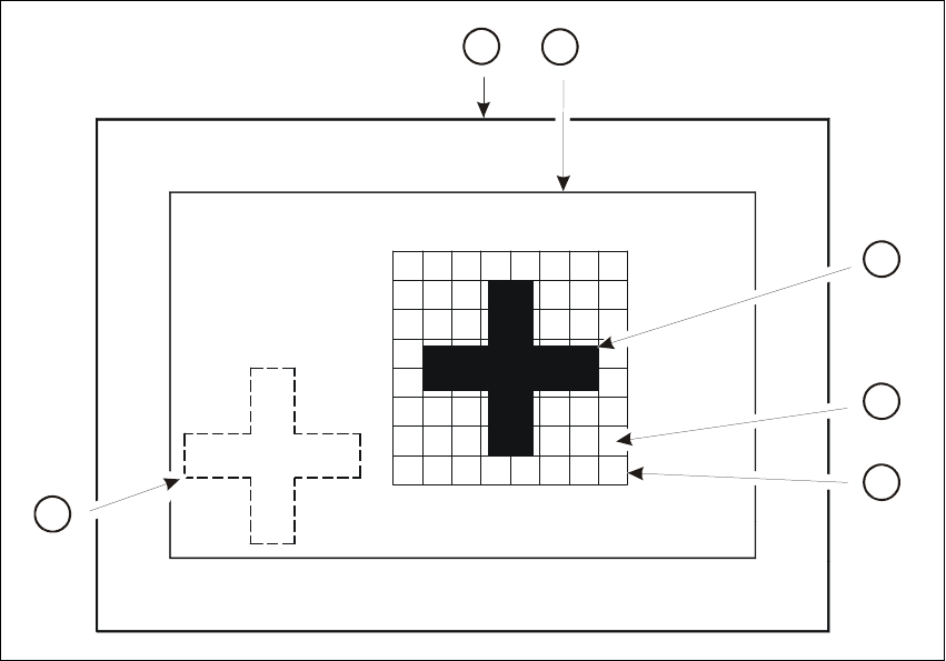
Fig. 6.2 - 1 Explanation of camera field of view, search area and template window
Key to Fig. 6.2 - 1
(1) Camera field of view
(2) Search area
≤
camera field of view (the fiducial is searched for in this area)
(3) Reference fiducial
(4) Moxel = pixel field, eg 16 x 16 pixels
(5) Template window (it contains the reference fiducial)
(6) Fiducial which is to be searched for
4
2
5
6
3
1