00191297-02.pdf - 第266页
6 Vision functions User Manual S-23 HM 6.6 Test Component Software Version SR.405.xx 05/ 99 Issue 264 6.6.4.10 Pin Dimension Opti on Use this option to c hange the optica l pin widt h and leng th. In ad dition, the pin c…
User Manual S-23 HM 6 Vision functions
Software Version SR.405.xx 05/99 Issue 6.6 Test Component
263
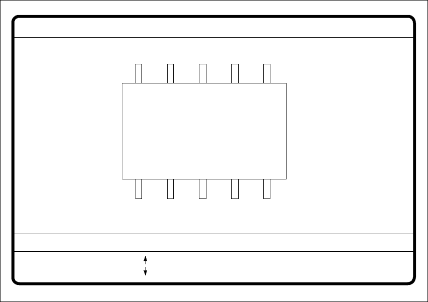
6.6.4.9 Package Dimension Option
There is potential for the occurrence of an effect called image reduction mainly with cylindrical
components, with PLCCs, BGAs and µBGAs. The reduction is caused by the round features of
the components that deflect incident light away from the camera sensor. Typically, the round
edges then become invisible to the camera. To remedy this problem, use the Package Dimension
option to change the optical package width and length to accommodate for the loss. 6
6
Fig. 6.6 - 27 Test component menu, Package dimension video image
È With the arrow keys you can change the length and width of the component. The current geo-
metric data will be displayed (see description on page 260).
È Use the spacebar to select different sides of the component.
È With the Return key you can trigger the individual measurement steps which are specified in
the measurement conditions.
È Press Esc to quit the option.
GF No. = 5
: larger
: smaller
RET: Test component
Blank: Pack. side
Pack. side = opt. l.[mm] = ... opt. w.[mm] = ...
Package dimension
6 Vision functions User Manual S-23 HM
6.6 Test Component Software Version SR.405.xx 05/99 Issue
264
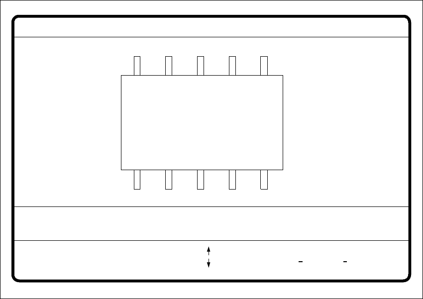
6.6.4.10 Pin Dimension Option
Use this option to change the optical pin width and length. In addition, the pin contrast can be
changed if imaging reduction results in the pins not being dependably recognized. 6
6
Fig. 6.6 - 28 Test component menu, Pin dimension option
È Use the tabulator key to select the pin model.
È With the spacebar select the side of the pin.
È Use the + and - keys to raise or lower the pin contrast.
È The arrow keys are used for changing the pin width and length. The component will appear as
a silhouette on the screen together with the updated geometric pin data.
È With the Return key you can trigger the individual measurement steps which are specified in
the measurement conditions for the specified component.
6
Press Esc to cancel the option, even if not all measurement steps have been carried out. You will
then be returned to the Test component menu. 6
GF No. = 5Pin dimension
+ : contrast +
opt. l. [mm] = ... opt. w. [mm] = ...
Pin side =
Pin definition = 1..n
RET: Test component
Tab: Pin model
Blank: pin side
Pin contrast =
: larger
: smaller
: contrast
User Manual S-23 HM 6 Vision functions
Software Version SR.405.xx 05/99 Issue 6.6 Test Component
265
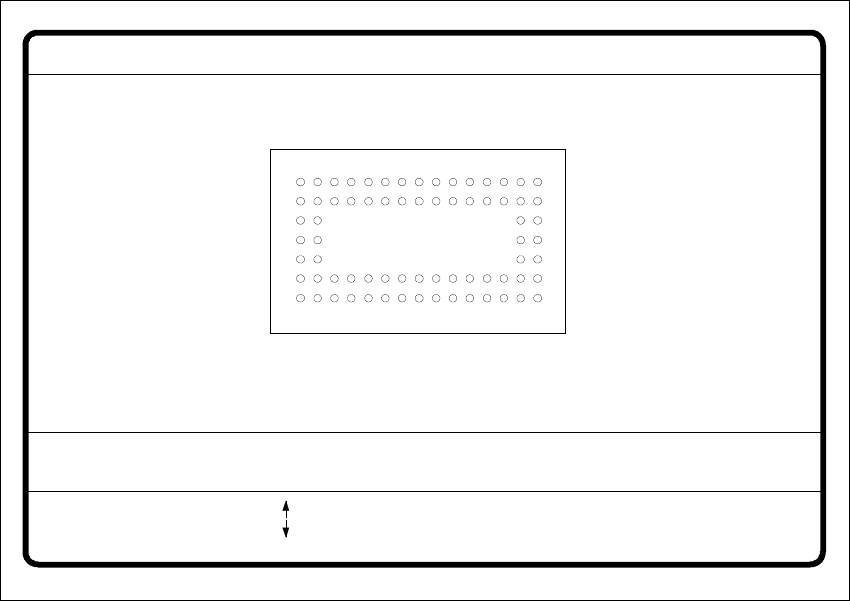
6.6.4.11 Ball Image Option
With this option you can change the ball model description. 6
6
Fig. 6.6 - 29 Test component menu, Ball image video image
È Use the tabulator key to select the ball model.
È With the spacebar select the radius type - inner or outer radius.
È Use the arrow keys to enlarge or reduce the internal or external radius of the ball. The balls will
be displayed in their geometric dimensions as a pixel image on the lefthand edge of the video
image.
The value of the inner radius the ball shape:
– If the inner radius is equal to 0, the ball will take the form of a circle.
– If the inner radius is greater than 0, the ball will take the form of a doughnut (not frequently
used).
È Use the + or - keys to increase or reduce the ball contrast.
Select ball contrast > 0, if the ball is lighter than the background.
Select ball contrast < 0, if the ball is darker than the background.
È With the Return key you can trigger the individual measurement steps which are specified in
the measurement conditions for the specified component.
GF no. = 5Ball image
RET: Test comp.
Tab: Ball model
Rad. i.[mm]
Ball model = 1
Rad. e.[mm]
Rad. type: intern./extern.
= 0.500
= 1.500
+ : Contrast +
- : Contrast -
Contrast a.
Contrast i.
= 10
= 20
: larger
: smaller
Blank: Radius type