3OM-1064-001.pdf - 第263页
0103-001 4-53-6 Tg0248-PM-ER 5. Component Recognition Error Code and List of Error Messages Error Code Display A Display B 20672032 COMPONENT DETECTION ERROR UNSPECIFIED LEADS ARE DETECTED. 20672033 COMPONENT DETECTION E…
0103-001 4-53-5 Tg0248-PM-ER
5. Component Recognition Error Code and List of Error Messages
Error Code Display A Display B
20660013 COMPONENT DETECTION
ERROR
WIDTH OF LEAD EXCEEDS THE TOLERANCE.
This error occurs when "MANUAL" is set in the "RECOG DATA SET" data box, "ENBL
(AUTO)" or "ENBL (MNL)" in the "LEAD WIDTH DETN" data box, and the lead width exceeds
its tolerance.
When "ENBL (AUTO)" is set in the "LEAD WIDTH DETN" data box, the tolerance is automati-
cally set.
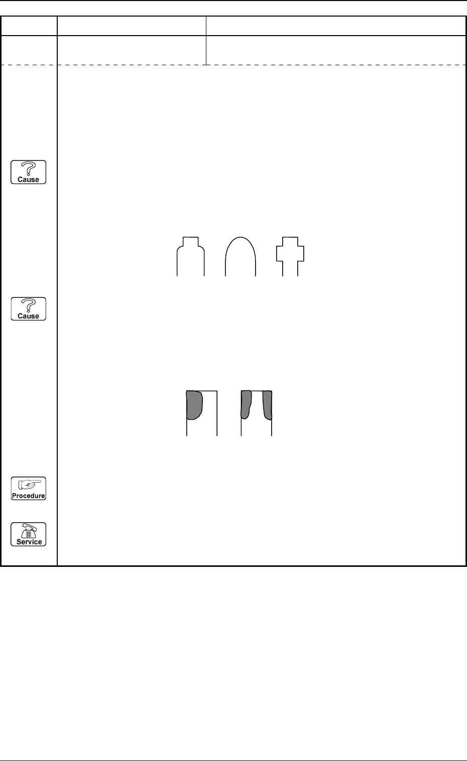
(Cause 1) The lead width is not suitable.
(This error occurs easily when the shape of the lead at the end looks as illustrated
below. When the shape of the lead looks as one of the followings, set "DISABLE" in
the "LEAD WIDTH DETN" data box.)
(Cause 2) The lead ends are not shining uniformly.
(This error may occur when the lead ends do not shine uniformly or are partly cracked
as shown below in the case of "Front Lighting". In this case, set "DISABLE" in the
"LEAD WIDTH DETN" data box or "MANUAL (FRONT LTG)" in the "LTG
MODE" data box to increase the brightness of the lighting and perform the recogni-
tion.)
(Reset Procedure in the case of Causes 1and 2)
Reset Procedure
(1) Press the [ZERO] button to return all the axes to their original positions.
(2) Re-start.
(3) If the device can’t be re-started, contact our service personnel.
0103-001 4-53-6 Tg0248-PM-ER
5. Component Recognition Error Code and List of Error Messages
Error Code Display A Display B
20672032 COMPONENT DETECTION
ERROR
UNSPECIFIED LEADS ARE DETECTED.
20672033 COMPONENT DETECTION
ERROR
SOME LEADS CANNOT BE DETECTED.
(Cause 1) The number of leads is not suitable.
(Cause 2) Objects shaped identically to the leads exist at both ends of the lead group.
(Cause 3) Dirt and dust have accumulated at both ends of the lead group.
(Reset Procedure in the case of Causes 1, 2 and 3)
Reset Procedure
(1) Press the [ZERO] button to return all the axes to their original positions.
(2) Re-start.
(3) If the device can’t be re-started, contact our service personnel.
(Cause 1) The number of leads is not suitable.
(Cause 2) The lead width is not suitable.
(Too large or small parameter is set in the "WIDTH" data box of the label "LEAD
DATA".)
(Cause 3) The leads look blurred.
(There is an extremely dark lead compared with other leads.)
(Cause 4) The direction of the component feed (direction of the component) is not suitable.
(Cause 5) Dirt, etc., have adhered to the cover glass in the fixed lighting unit.
(This can be checked through the recognition monitor.)
(Reset Procedure in the case of Causes 1, 2, 3, 4 and 5)
Reset Procedure
(1) Press the [ZERO] button to return all the axes to their original positions.
(2) Re-start.
(3) If the device can’t be re-started, contact our service personnel.
0103-001 4-53-7 Tg0248-PM-ER
5. Component Recognition Error Code and List of Error Messages
Error Code Display A Display B
20672034 COMPONENT DETECTION
ERROR
THE LEAD-TO-LEAD DISTANCE AT BOTH ENDS OF
LEAD GROUP EXCEEDS THE TOLERANCE.
20672036 COMPONENT DETECTION
ERROR
LEAD GROUP NOT FOUND.
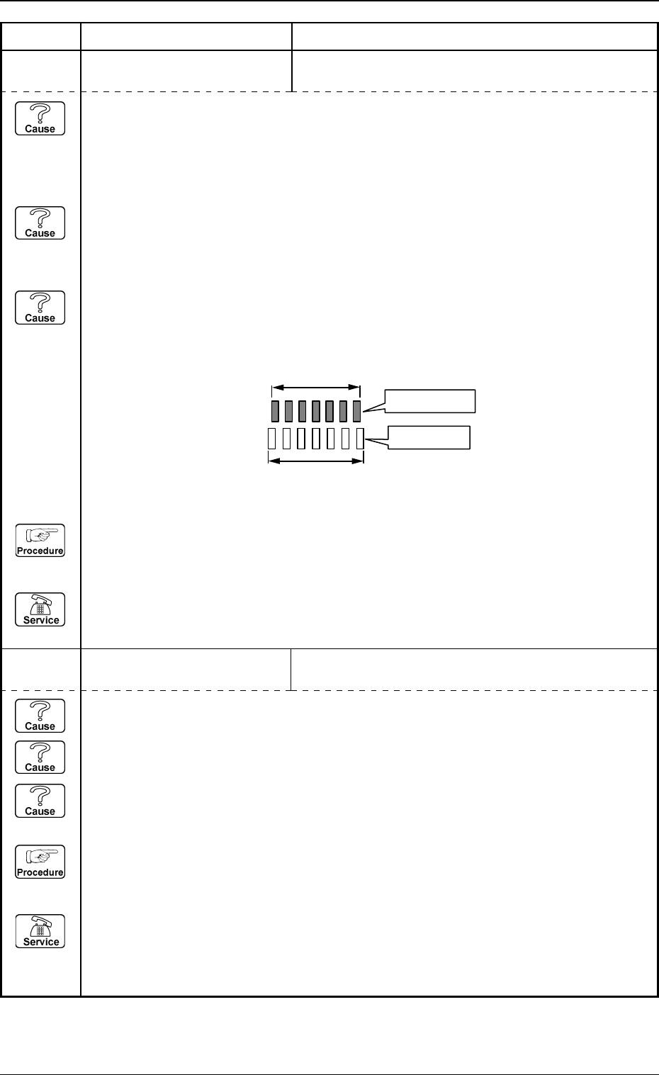
(Cause 1) The lead pitch is not suitable.
(When the lead pitch is different, this kind of error occurs more frequently on a compo-
nent with more leads because it has a bigger accumulated pitch error, compared with a
component with less leads.)
(Cause 2) The component thickness is not suitable.
(The lead-to-lead distances at both ends of the lead group become wider or narrower
because the entire image of the component looks larger or smaller than the actual size.)
(Cause 3) The camera magnification is not suitable.
(When four cameras are individually used to perform component recognition tests on
the component and this type of error occurs in only one camera, the camera magnifica-
tion may be wrong.)
(Reset Procedure in the case of Causes 1, 2 and 3)
Reset Procedure
(1) Press the [ZERO] button to return all the axes to their original positions.
(2) Re-start.
(3) If the device can’t be re-started, contact our service personnel.
Actual Component
Component Data
(Cause 1) No component is picked up.
(Cause 2) A different component (small component, etc.) is picked up.
(Cause 3) The lighting is not ON.
(Reset Procedure in the case of Causes 1, 2 and 3)
Reset Procedure
(1) Press the [ZERO] button to return all the axes to their original positions.
(2) Re-start.
(3) If the device can’t be re-started, contact our service personnel.