3OM-1064-001.pdf - 第36页
Operation Procedure (1 ) Select one of the “DIRECTION” keys ([ ], [ ], [ ], and [ ]) to determine the direction in which the X/Y beam is moved to the position where the actual fiducial mark can be located at the center o…
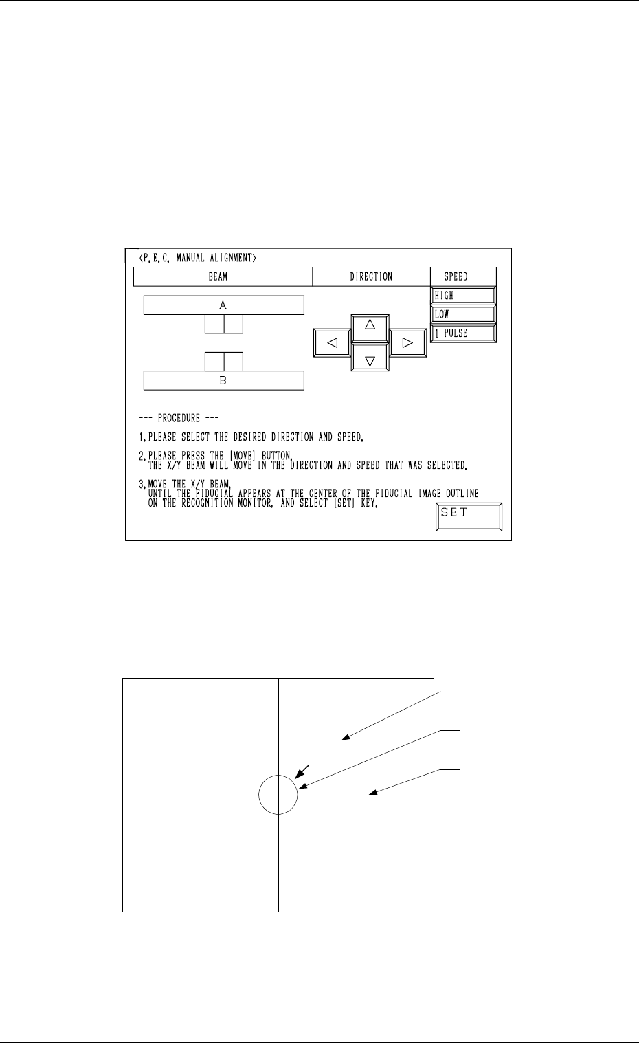
5. Cancellation of P.E.C. Recognition Error
When the [RESET] button is pressed after a P.E.C. recognition error has oc-
curred during automatic operation, the “MANUAL ALIGNMENT” display
(Fig. 1.4 or 1.5) appears on the screen.
The display on the screen and the operation procedures differ according to the
mode set at “P.E.C. MANUAL ALIGNMENT MODE”. (Hierarchical Se-
quence: “AUTO OPN MODE (PLACEMENT)” Display → “AUTO OPN SUB-
MENU” Display → “OPERATION MODE” Display → “P.E.C. MANUAL
ALIGNMENT MODE” Display)
P.E.C. Manual Alignment Mode: STANDARD
Fig. 1.4
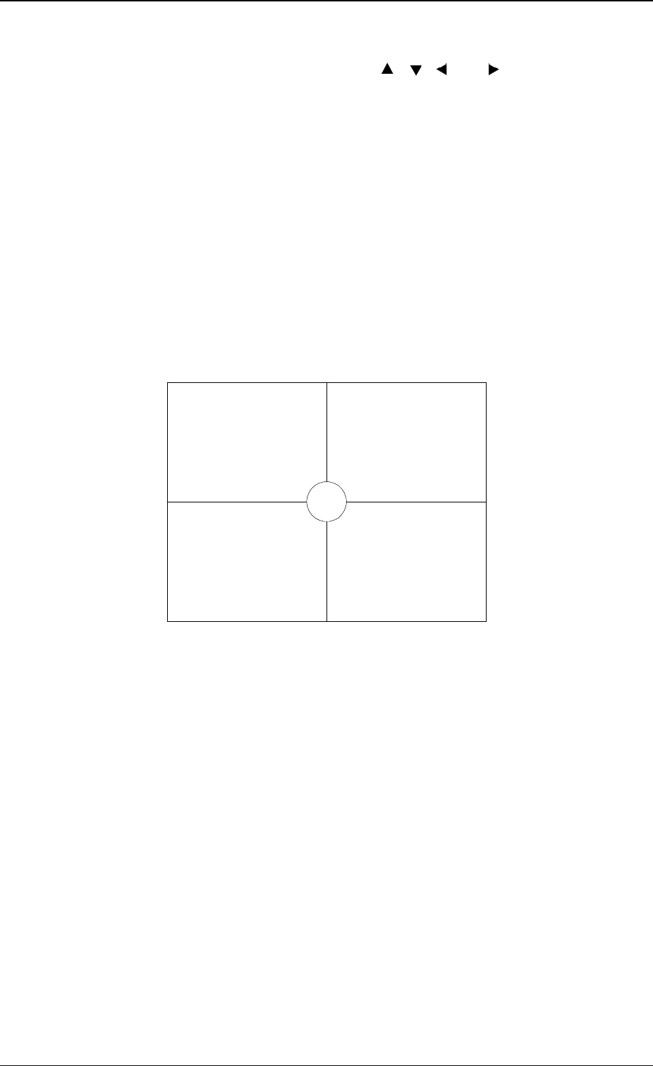
An image of the captured fiducial mark appears in the crossline section and a
template (identical to the fiducial mark in shape and size) at the center of the
crosslines on the recognition monitor.
(See Fig. 1.5.)
Fig. 1.5
The X/Y beam must be moved until the image of the actual fiducial mark and
the template overlap each other at the center of the crosslines. (Manual Align-
ment)
Actual Fiducial Mark
Template
Crossline
0005-002 1-27 Tg0248-PM-ER
5. Cancellation of P.E.C. Recognition Error
Operation Procedure
(1) Select one of the “DIRECTION” keys ([ ], [ ], [ ], and [ ]) to determine
the direction in which the X/Y beam is moved to the position where the
actual fiducial mark can be located at the center of the crosslines. Then,
select one of the “SPEED” keys ([HIGH], [LOW], and [1 PULSE]) and
press the [MOVE] button.
When the [HIGH] or the [LOW] key is selected, the X/Y beam keeps on
moving at the selected speed as long as the [MOVE] button is kept pressed.
Every time the [1 PULSE] key is pressed, the X/Y beam moves in the
increments of 1 pulse.
(2) While changing the direction and speed, move the XY beam until the im-
age of the actual fiducial mark and the template overlap each other at the
center of the crosslines as shown in Fig. 1.6.
Note: Perform the manual alignment operation perfectly with the [1
PULSE] key (one of the “SPEED” keys). Otherwise, components
may not be placed accurately.
Fig. 1.6
(3) After the completion of the manual alignment operation, press the [END]
key.
The “AUTO OPN MODE (PLACEMENT)” display appears on the screen.
(4) When the [START] button is pressed, the automatic operation re-starts.
Note: Pressing the [END] key is validated only once after manual alignment
operation is completed.
• Exiting from Manual Alignment Operation by Mistake
If the [END] key is pressed by mistake, a placement position error occurs.
When placement position deviates from the correct one, follow the reme-
dial operation described below.
Operation Procedure
(1) Press the [SYS CLR] button to interrupt automatic operation.
(2) Perform zeroing operation.
(3) Open the “AUTO OPN SUB-MENU” display and perform the semi-au-
tomatic operation to re-start the operation. (Hierarchical Sequence: “AUTO
OPN MODE (PLACEMENT)” Display → “AUTO OPN SUB-MENU”
Display)
0005-002 1-28 Tg0248-PM-ER
5. Cancellation of P.E.C. Recognition Error
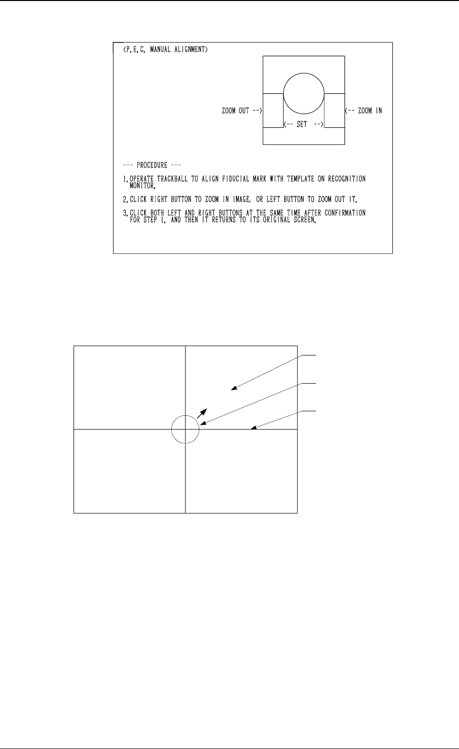
P.E.C. Manual Alignment Mode: TRACKBALL
Fig. 1.7
A template (identical to the fiducial mark in shape and size) appears at the
center of the crosslines on the recognition monitor.
(See Fig. 1.8.)
Fig. 4.8
Fig. 1.8
The center of the crosslines must be moved using the trackball until the image
of the actual fiducial mark and the template overlap each other.
(Manual Alignment)
Actual Fiducial Mark
Template
Crossline
0005-002 1-29 Tg0248-PM-ER
5. Cancellation of P.E.C. Recognition Error