3OM-1064-001.pdf - 第33页
4. Cause and Remedy of Beam Abnormal Approach Detection Whenever a beam abnormal approach error is detected, the machine stops in- stantaneously in an error condition and an error message is issued regardless of machine …
3. Cause and Remedy of Nozzle Excessive Pushing
Error
Whenever a nozzle excessive pushing error is detected, the machine stops in-
stantaneously in an error condition and an error message is issued regardless
of machine operation mode (“RUN”, “PAUSE”, or “STOP”) because machine
protection has top priority.
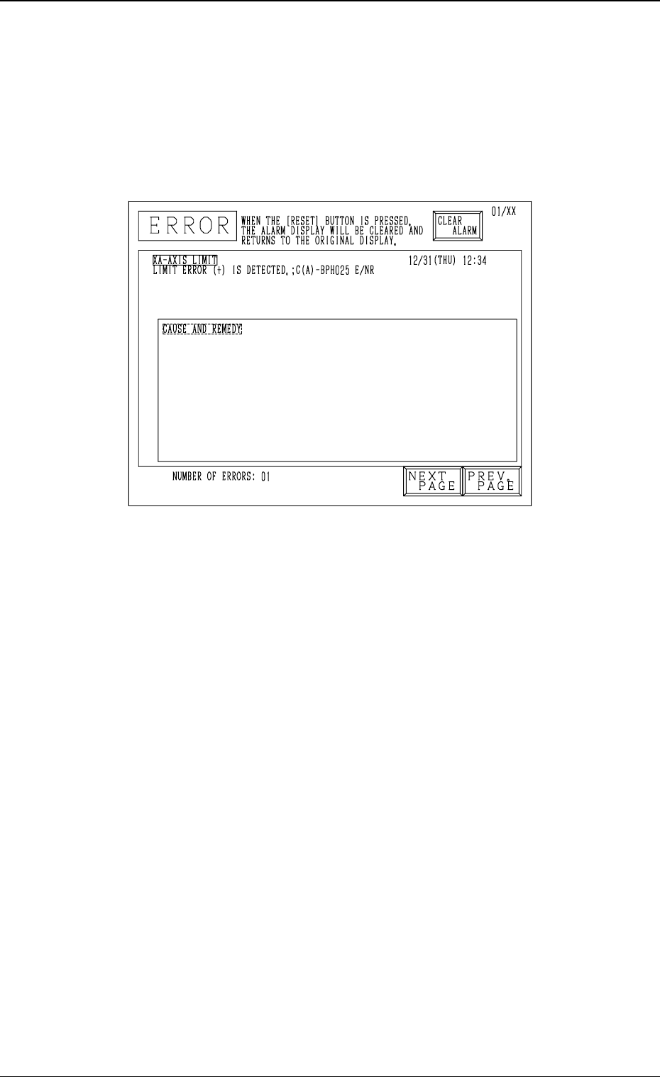
Fig. 1.2
Cause of Nozzle Excessive Pushing Error
• A value different from the actual height is entered as “HEIGHT” data in the
component library data.
• A value different from the actual nozzle length is entered as “LENGTH”
data in the nozzle data.
• The offset data is illegal.
• The machine tried to place a component on a previously-placed one due to
an error, etc., in the pattern program.
Remedy
(1) Press the [RESET] button to cancel the error condition.
(2) Zero the up/down shaft.
(3) Remove the cause of the error.
(4) Zero each shaft.
(5) Re-start the operation.
0005-002 1-24 Tg0248-PM-ER
3. Cause and Remedy of Nozzle Excessive Pushing Error

4. Cause and Remedy of Beam Abnormal Approach
Detection
Whenever a beam abnormal approach error is detected, the machine stops in-
stantaneously in an error condition and an error message is issued regardless
of machine operation mode (“RUN”, “PAUSE”, or “STOP”) because machine
protection has top priority.
It is almost impossible for this kind of error to occur.
Whenever this error occurs, it is assumed that Beams A and B might have
collided each other. In this case, contact our marketing department.
Fig. 1.3
Cause of Beam Abnormal Approach Detection
• There is an error in the system.
• A mechanical shift has occurred.
When Beams A and B did not collide with each other, follow the procedure
below to reset the machine to the normal condition.
Note: The P.C.B. in the middle of process (production) cannot be handled
successively. To re-start the operation, open the “AUTO OPN SUB-
MENU” display and follow the semi-automatic operation. (Hierarchi-
cal Sequence: “AUTO OPN MODE (PLACEMENT)” Display →
“AUTO OPN SUB-MENU” Display)
0005-002 1-25 Tg0248-PM-ER
4. Cause and Remedy of Beam Abnormal Approach Detection

Remedy
(1) Press the [RESET] button to cancel the error condition.
(2) Press the [READY] button to unlock the supply cover.
(3) Open the safety bar and the supply and maintenance covers. Then, push
Beams A and B by hand to separate them.
(4) Close the maintenance and supply covers and the safety bar.
(5) When an error occurs, check the contents of the error and remove the
cause.
(6) Press the [POWER ON] button for approx. 2 seconds to supply power to
the loads.
(7) Press the [RESET] button to cancel the error condition.
The system clear operation is executed.
(8) Press the [READY] button to lock the supply cover.
(9) Press the [ZERO] button to zero each device.
After all devices are zeroed completely, open the “AUTO OPN SUB-
MENU” display and perform the semi-automatic operation to re-start the
operation. (Hierarchical Sequence: “AUTO OPN MODE (PLACE-
MENT)” Display → “AUTO OPN SUB-MENU” Display)
0005-002 1-26 Tg0248-PM-ER
4. Cause and Remedy of Beam Abnormal Approach Detection