CM88Maintenace2x.PDF.pdf - 第105页
Page 1-13 CALIBRA TION 3Y3C-E-MMZ0A-A01-02 Pickup Position Calibration 5 . T urn OFF the servo switch. 6 . Open the rear center safety cover . 7 . Set the camera jig onto the table. 1. Remove the cover from the camera ji…
Page 1-12
3Y3C-E-MMZ0A-A01-01
Pickup Position Calibration
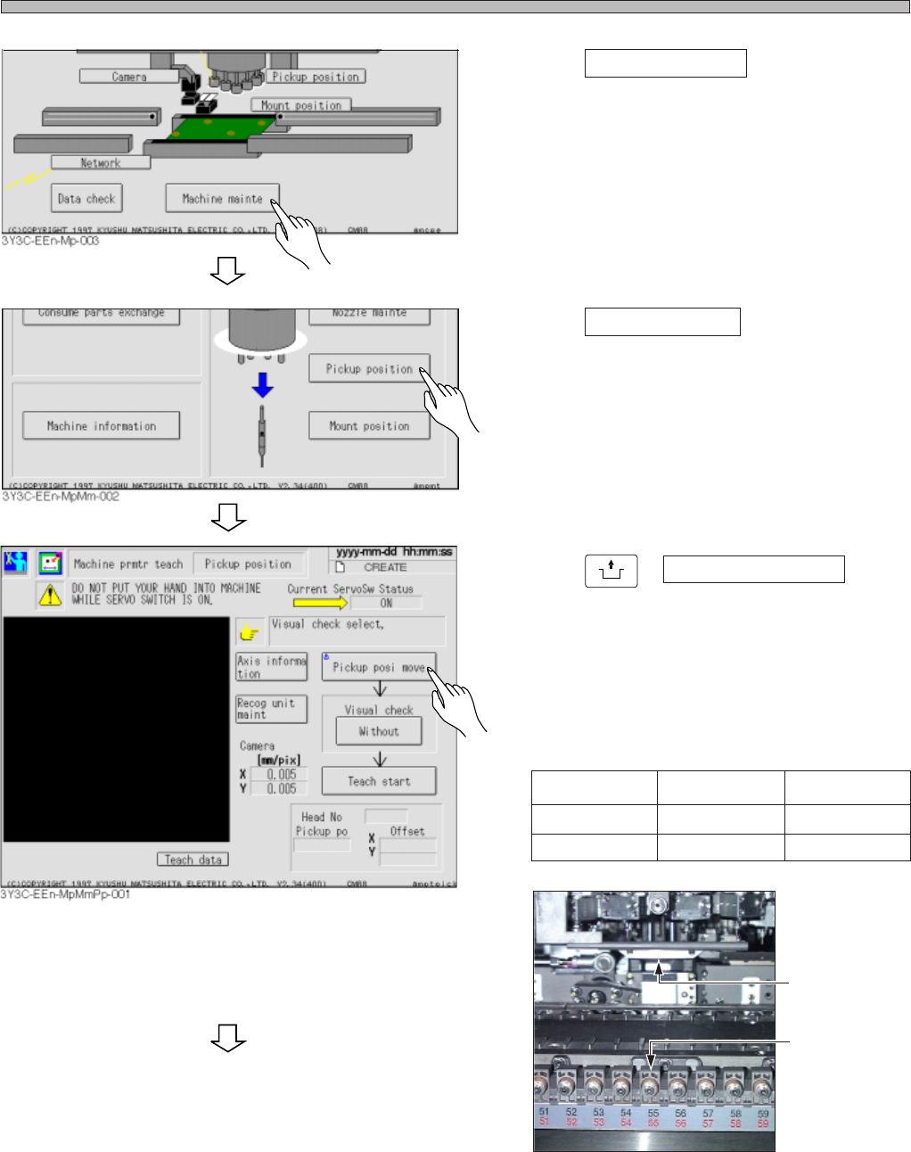
2. Press Machine mainte .
3. Press Pickup position .
4. Press
UNLOCK
+ Pickup posi move .
• The table moves so that the feeder axis No. 55
(CM88S-M/MU) and No. 20 (CM88S-M1) on
the A stage will be the pickup position.
∗ Be careful of the pickup position according to
the time when you get the machine.
Pickup Position
3Y3C-142P
No.55
CM88S-M/MU
55
48
CM88S-M1
20
9
To May, 2000
From May, 2000
To the next page
Page 1-13
CALIBRATION
3Y3C-E-MMZ0A-A01-02
Pickup Position Calibration
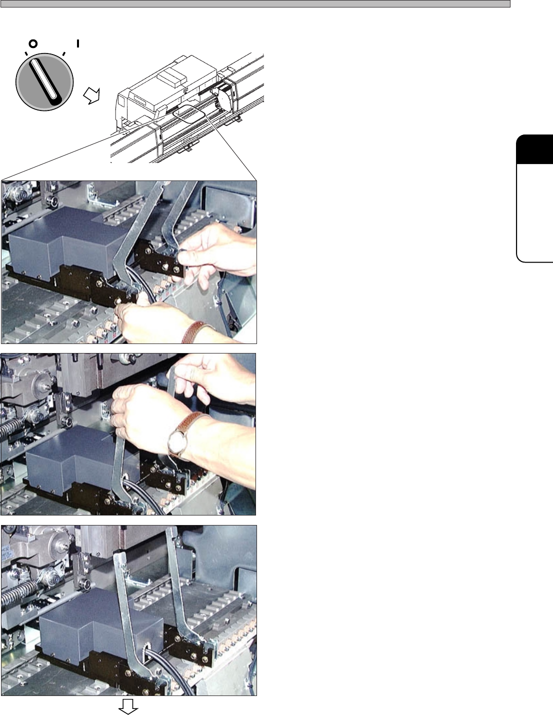
5. Turn OFF the servo switch.
6. Open the rear center safety cover.
7. Set the camera jig onto the table.
1. Remove the cover from the camera jig, then
put the jig onto the table. At this time, the
center of the jig should be at the pickup
position.
• The center of the camera jig should be the
following position.
CM88S-M : No.48
CM88S-M1 : No.9
∗ Make sure that no dust is stuck on the setting
side between the table and the camera jig.
∗ When setting and removing the camera jig, be
careful that the jig does not interfere with the
nozzles on the head.
2. Push the toggle levers.
(The picture on the left indicates the state that
the levers are set.)
OFF ( )
ON ( )
SERVO
3Y3C-143P
3Y3C-144P
3Y3C-145P
3Y3C-AI01
To the next page
Page 1-14
3Y3C-E-MMZ0A-A01-00
Pickup Position Calibration
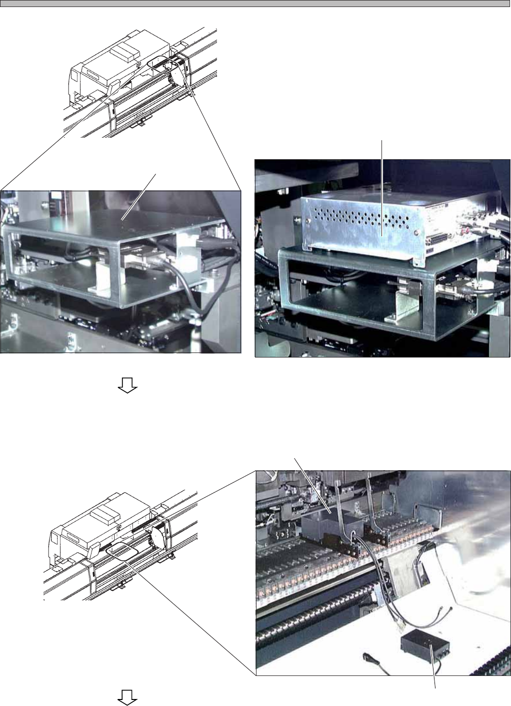
8. Put the CCU onto the setting position.
9. Put the power supply box onto the
setting position.
Setting Position
Power Supply Box
Camera Jig
3Y3C-146P
3Y3C-147P
3Y3C-148P
3Y3C-AI01
3Y3C-AI01
To the next page
CCU